-1

I have read that TDR is problematic because if we have many transmission lines in series which cause discontinuity to the source resistance ,then the closer TL's will mask the reading of the far TL from the source, so is when the rise time of the source is larger the TL delay.

So what is the alternative to the TDR? what method is used to overcome those problems and see the impedance at every location of the system?

An example is shown in the picture below. We have 80 Ω, 30 Ω and 50 Ω transmission lines. The 80 Ω and 30 Ω t-lines create masking problem for reading the 50 Ω transmission line: -
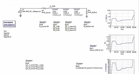
enter image description here

Andy aka
  • 456,226
  • 28
  • 367
  • 807
ron398
  • 157
  • 1
  • 8
  • Ron this can be easily simulated so, if you have a specific scenario, you should detail it. – Andy aka Mar 14 '21 at 15:09
  • Hello Andy,Hello in the link bellow you can see a system of 80 ,30 50, where the source impedance is 50,as you can see the TDR method is suffering from masking. How do you overcome this problem? Is there some alternatie method?

    https://ibb.co/LnZQ214

    – ron398 Mar 14 '21 at 15:19
  • If you have a specific problem to solve, why don't you add it into your question and also state why you believe the response graphs to be problematic in masking certain things. Then have you considered that you can use different pulse widths to overcome some or maybe all masking problems? – Andy aka Mar 14 '21 at 15:24
  • I've simulated the scenario but I see your done now. The effect of the open circuit at the end of the 50 ohm line is clearly seen so I don't know why you think it won't be. – Andy aka Mar 14 '21 at 15:57
  • Hello Andy ,ok if we change the 80 to 100 then the 50 will be masked, the pulse width has no effect because DC doesnt have any effect on TDR on the change in voltage. Is there some alternative simulation method for overcoming masking? – ron398 Mar 14 '21 at 16:14
  • You just analyse the received data for a longer period and you get a totally different result but this question is done now. – Andy aka Mar 14 '21 at 16:22

1 Answers1

3

You can use a VNA to measure the frequency domain reflection, and use post-processing of the signal to obtain the equivalent TDR trace, as your previous question implies you are already considering. This method will still suffer somewhat from multiple reflections but may be more effective for several reasons:

  • The VNA stimulus delivers equal power at all frequencies, whereas in TDR the power falls as \$1/f\$, leading to quite weak signals and low SNR at the higher part of the desired frequency band.

  • The VNA can be set up to average its measurement over a long time at each frequency, improving the SNR dramatically. TDRs can also use multiple-trace averaging, but the amount of averaging that is practical is less than when using a VNA.

  • The VNA receiver is simply more sensitive than the receiver (oscilloscope input) typically used with a TDR.

That said, if you want to separate the reflections from discontinuities that are very far apart in physical space, with a VNA-based "TDR" measurement, you need to have a VNA capable of measuring at both very low and very high frequencies. Many VNAs have minimum frequencies that might be too high for some systems that could be easily measured with a TDR.

The Photon
  • 129,671
  • 3
  • 164
  • 309
  • Hello The Photon,In the real world i understand,what about simulation method. how we overcome masking? – ron398 Mar 14 '21 at 16:12
  • @ron398, I don't understand. Your question doesn't ask anything about a simulation method. But generally simulations can be done noise-free (aside from numerical precsision issues) so there isn't any concern. – The Photon Mar 14 '21 at 16:15
  • Yes you are correct the simulation is still transient simulation.I am asking about solution to masking when i am doing a simulation.Is there some trick i could do so the 50 ohm TL wont be masked in the transient impedance plot? Thanks. – ron398 Mar 14 '21 at 16:17
  • @ron398, in the simulation, you must already know what transmission line elements are present in your system in order to do the simulation. What problem are you trying to solve? – The Photon Mar 14 '21 at 16:29
  • The problem is that the most distanced transmission line value is dostorted in the TDR transient plot result ,because of the other two TL's in the simulation.this is a kknown phenomena called masking. you proposed a great solution in the real world to use VNA. But is there some alternative solution in the simulation shown in the link?Thanks. https://ibb.co/LnZQ214 – rocko445 Mar 14 '21 at 17:14
  • 1
    @rocko445, the simulation is showing you how the real circuit would behave. Masking happens in the real world, so if the simulation didn't predict masking, it would be a wrong simulation. If the simulation doesn't show masking then it is wrong. Again, I'm not clear what problem you're trying to solve. In the real circuit, you use TDR to try to work out what discontinuities are present in a circuit/system that you don't have complete knowledge of (and masking might make this more difficult). But in simulation, you already know what the circuit is...so what are you trying to accomplish with TDR? – The Photon Mar 14 '21 at 17:25
  • Hello the Photon,So the pulse TDR method will show masking in scope too in the real world. So the only way to eliminate masking is to use VNA. Correct? – rocko445 Mar 14 '21 at 17:38
  • 1
    @rocko445, even with the VNA, the masking will be there. But the better SNR will make it easier to work out what features in the TDR trace came from what features in the physical system. If you want to eliminate masking the only thing you can do is use your TDR or VNA on a simpler physical system that doesn't produce so many overlapping reflections. – The Photon Mar 14 '21 at 17:40
  • Thank you very much – rocko445 Mar 14 '21 at 17:42