As with your previous question, I believe you should approach this problem as a limit approach of increasing Rc. Moreover, you might gain some benefit from comparing two similar, but very different from the point of view of the base current, configurations.
A common emitter where current limiting is done via a base resistor, and an emitter degenerated configuration where current limiting is done by an emitter resistor.
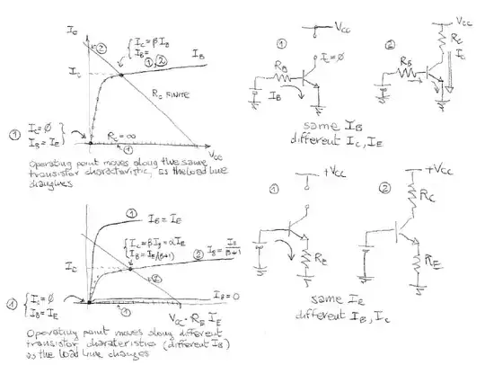
For the moment I'll just add the following picture

The second configuration is explained in more detail in the above linked question. In terms of load lines, you want to know what happens when you switch from a finite Rc (the slanted load line denoted by (2) on the graphs) to an open circuit (the horizontal load line denoted by (1) on the graphs, and highlighted by ticks).
As you can see the operating point goes from the active zone (I suppose the finite value of Rc was enough to keep the transistor out of saturation) to the point with Ic = 0 (and ideally Vce = 0 with a perfect transistor, let's not get into this level of detail). The big difference is that in one case Ib is a negligible contribution to Ie, while in the other Ib is nearly almost all of Ie.
If we go by the approximation Vbe=0.7V in active region, in the common emitter case with base resistor Rb we have that Ib is constant and equal to (Vbb - 0.7V)/Rb, while Ic and Ie change as Rc changes; in the other case with emitter resistor Re, it is the emitter current that remains constant at (Vbb - 0.7V)/Re while Ib and Ic change as Rc changes, as show in the graph in my other answer. (Vbb is the base battery voltage)
Finally, the reason you are confused is that by removing all resistances you have put yourself in a nearly impossible situation when you switch from Rc=0 to Rc=infinity.
If you keep a base current limiting resistor (either as Rb or as Re) then the above graphs and reasoning still apply, with the only alteration that the case Rc=0 will see the load line (2) as a vertical line.
But if you remove all limiting resistors then you will have a vertical load line on the base circuit as well, and you need a very precise Vbb to avoid exceeding the maximum base current limit. In theory, with an ideal transistor with an ideal base diode (vertical characteristic at Vbe, the one we used as an approximation to easily compute base current and emitter current in the two circuits above) any value higher than the exact value required will cause an infinite current and the destruction of the transistor. So, either you consider the exact nonlinear characteristics of the BJT (which, due to the steep nonlinearity will give little leeway before you kill the device), or you add limiting resistors and see what happens in the limit when their values go to zero (or to infinity in the case of Rc).


