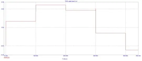
I am using a signal generator to generate a long square pulse that is fed into a long transmission line consisting of two parallel wires. The transmission line is approximately 1km long. The near end is terminated with a 25\$\Omega\$ resistor, and the far end is unterminated. With an ADC I am sampling the incoming signal.
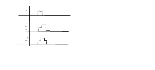
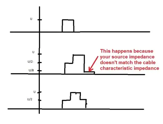
In the below diagram you can see the square pulse (1) I am feeding into the transmission line. (2) shows the signal I measured with the ADC. You can see that the first plateau is at U/2. The 2nd plateau is really small and almost not there.
I would have expected a incoming signal like shown in (3). I don't understand why the plateaus shown in (2) are not at the same voltage level.
Does anyone have an idea?
In the diagram I neglected the attenuation of the cable.
