0

I have a 100W D class amplifier that runs on 24V. It uses 2 x TPA3116D2 IC for amplification. I also have a 24V 16A power supply. I need to provide a soft start circuit for this, because the amplifier is not protected from pops and clicks. I came up with the circuit below. It uses parts that I already have at hand. I ran a simulation and it seems to be right, but I have doubts.

I was not working with electronics in the last 6 months, and I'm not too familiar with analog circuits. I wanted to get an opinion before I built this circuit. I don't need a complete analysis, just a quick look. Does it have some obvious design flow? Is there anything that must be changed in order to work?

Thanks

ADD: One answer suggested modifying the amp instead of the power supply circuit. The amp is commercial product. I do not want to make any modifications to it."

schematic

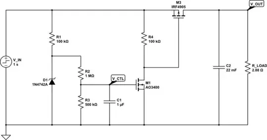
simulate this circuit – Schematic created using CircuitLab

nagylzs
  • 390
  • 5
  • 14
  • I think I need another 1N4742A zener between M1 drain and M3 gate, so that the gate of M3 will never go below -12V. (Absolute maximum is -20V) – nagylzs Nov 21 '20 at 18:23

4 Answers4

1

Overall, ok. But ...

  1. R1 is a bit large. Decreasing it to 10K will increase the zener current to a little over 1 mA, a better number for stable regulation.

  2. R2 and R3 form a 2:1 divider that decreases the M1 max. gate voltage to only 4 V. I would adjust R2, R3, and C1 so the max gate voltage is in the 8V to 10 V range, while maintaining the time constant you want for the turn-on slope.

The gain of M1 acts to speed up the voltage slope at its gate, and output transistor M3 speecs it up even more. The output voltage ramp might be faster than you expect

You can eliminate M1 by placing the timing components around M3. C1, D1, and the discharge resistor between the gate and source, and the timing resistor between the gate and GND

AnalogKid
  • 19,998
  • 1
  • 13
  • 32
  • Updated schematic, lowered R1 to 10k. The thresold voltage ot AO3400 is about 1V, the 4V gate voltage is more than enough to turn it on. Although it can withstand Vgs=12V so maybe I'll change the divider a bit, just to be on the safe side. – nagylzs Nov 21 '20 at 19:17
  • Instead of eliminating M1, would it be a better solution to put a capacitor between M3 gate and GND? – nagylzs Nov 21 '20 at 19:18
  • @nagylzs NO, don't update the schematic in your question - this isn't a forum or talking shop and questions are not liked when they evolve - it's a Q and A site so now, anyone coming along won't be able to relate the question to the answers. If you want to make a circuit update, post it on Imgur and link in comments. – Andy aka Nov 21 '20 at 19:38
  • All right, update removed – nagylzs Nov 21 '20 at 19:49
1

Right at the instant you apply power and, due the the drain source capacitance of M1, you will get a thin pulse of current through M3. This might not be a problem of course but you can avoid this with a 10 nF across R4.

Regards R4 being 100 kΩ and the leakage current of M1 being around 1 μA, there might be just enough residual voltage developed across R4 that M3 may turn on a little bit and not give exactly what you want so, I'd lower R4 to 10 kΩ.

In case you get a power drop-out that lasts (say a second or so) I'd put a discharge diode from the gate of M1 to the positive rail so that if the rail is lost, you rapidly discharge the delay capacitor C1.

Of course you may be able to get away without M1 completely and just have a resistor to ground and a biggish capacitor between source and gate of M3.

You'll also put a zener between gate and source of M3 to protect it too.

Andy aka
  • 456,226
  • 28
  • 367
  • 807
1

Some things:

  1. does fet M3 really stand -24V Vgs when M1 conducts?

  2. insert something which keeps the power OFF until Vin has really stabilized. And runs also power down if Vin has a blackout

  3. The Amp IC has mute and shutdown. Consider to use them to silence the amp if the power is not OK, you will not need a high current fet, only a power condition detector.

  • Unfortunately, the amplifier is a commercial product with manufacturer guarantee and its own metal case. I don't want to make modifications to the amplifier. Updated the schematic, added a zener to limit Vgs to -12V. – nagylzs Nov 21 '20 at 19:13
1

Here is a ((concept)) schematic of the approach I described. Your post does not say what kind of delay or ramp time you want. As shown, the time constant is about 180 ms, but the ramp time to full enhancement is less than that.

enter image description here

AnalogKid
  • 19,998
  • 1
  • 13
  • 32
  • This is much more simple. It is also protected from blackouts through D1. You used IRFR9024. It has a less steep on-slope than IRF4905, I might need to adjust some values. I think I'll try this first because of its simplicity. – nagylzs Nov 22 '20 at 07:15
  • This is a ((concept)) schematic; I'm not recommending that particular FET. The components are what is already in my design libraries from past projects – AnalogKid Nov 22 '20 at 14:18
  • Accepted this because much more simpler and works. I did not try the other suggested modifications. – nagylzs Nov 24 '20 at 19:15