6

I want to connect a 3.3V TFP401 to a 2.5V spartan 6 LX45T FPGA. It looks like each device is tolerant to the other device's voltage:

TFP401:

DVDD                                      Min: 3.0V   Nom: 3.3V  Max: 3.6V
Input voltage range, logic/analog signals Min: –0.3V  Max: 4V
High-level digital input voltage(1)       Min: 2V     Max: DVDD  
Low-level digital input voltage(1)        Min: 0V     Max: 0.8V

Xilinx Device:

xilinx

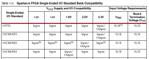
This means that both are going to be transmitting at their respective voltages and are tolerant to receiving at the opposite voltage. I can't see anything wrong with this?

I'm just not sure about one thing: Do I have to be concerned about current drive strengths? If a device drive current is spec'ed to drive a voltage to 2.5V within a specified time, and the receiving device expects a 3.3V input with different high/low thresholds, then the input slew rate could possibly be out of spec since the signal takes longer to be detected as "high" on the receiving end?

I don't think this is a big issue because I can specify in my timing that the signal is a LVCMOS33 signal on a 2.5V line and the FPGA can compensate accordingly. Also I can change the drive strength on the FPGA as needed. I just want to be sure that this is really the case.

Clarification: At the moment my intention is to use LVCMOS33 for inputs and LVCMOS25 for outputs. I've never seen this done before. Good idea, bad idea?

Edit 1: Implications of using LVCMOS25 for in and out:

Case 1: FPGA out, TFP401 in.

FPGA out 2.5V. 
    FPGA   Output Low   is 0.4V max
    FPGA   Output High  is 2.1V min

TFP401 in 3.3V. 
    TFP401 Input  low   is 0.8V max <-- Fine.       FPGA out low  is below TFP by 0.4V.
    TFP401 input  high  is 2.0V min <-- Borderline. FPGA out high is above TFP by 0.1V.

Case 2: TFP401 out, FPGA in.

TFP401 out 3.3V. 
    TFP401 Output low   is 0.8V max
    TFP401 Output high  is 2.4V min

FPGA in is 2.5V. 
    FPGA   Input  low   is 0.7V max <-- Problem. TFP out low  is above FPGA by 0.1V.
    FPGA   Input  high  is 1.7V max <-- Fine.    TFP out high is above FPGA by 0.7V.

FPGA numbers taken from here, page 10.

TFP401 numbers taken from datasheet linked in first line.

stanri
  • 5,382
  • 2
  • 29
  • 56
  • Out of curiosity, why are you powering your FPGA with 2.5V and your peripherals with 3.3V? – embedded.kyle Dec 06 '12 at 14:02
  • It's just one particular peripheral that is a 3.3V device. Almost all other devices are 2.5V except for the sdram which is 1.8V and has its own bank. I can't justify allocating an entire FPGA bank just to one peripheral, it would be a waste of pins. – stanri Dec 06 '12 at 15:04

1 Answers1

1

If I'm reading your question correctly, it sounds like you plan to set the pins on the FPGA as outputs and configure them with the LVCMOS33 standard. That won't work. If you take a look at Table 1-5 in your question, you will see that LVCMOS33 is not compatible as an output with a Vcco of 2.5V. Only as an input. With a Vcco of 2.5V your outputs need to all be LVCMOS25.

If I remember correctly, the I/O standard, drive strength and slew rate are on a per bank basis. So you may want to separate your inputs and outputs into separate banks so that you can use the LVCMOS33 standard on your inputs.

That being said, fast slew rates and high drive strengths are not always the best option. They can cause problems of their own. Slower transitions reduce the effects of reflection and lower drive strength will reduce ground bouncing.

To start with, I would just leave it at the defaults of LVCMOS25, Slow Slew Rate, and 12mA Drive Strength. Only adjust if you have problems. Personally, I've rarely had to change these in practice when communicating with chips. And only rarely when driving discrete transistors. But I've also never really done anything that can be considered high-speed.

From the Spartan-6 FPGA SelectIO REsources:

High output current drive strength and FAST output slew rates generally result in the fastest I/O performance. However, these same settings can also result in transmission line effects on the PCB for all but the shortest board traces. Each IOB has independent slew rate and drive strength controls. Use the slowest slew rate and lowest output drive current that meets the performance requirements for the end application.

Besides that the TFP401 seems to be designed to handle a certain amount of skew on the data channels:

In addition, skew between the three data channels is common. The TFP401/401A uses a 4× oversampling scheme of the input data streams to achieve reliable synchronization with up to 1-tpix channel-to-channel skew tolerance. Accumulated jitter on the clock and data lines due to reflections and external noise sources is also typical of high-speed serial data transmission; hence, the TFP401/401A design for high jitter tolerance.

embedded.kyle
  • 8,511
  • 2
  • 26
  • 45
  • I was considering using outputs as LVCMOS25 and inputs as LVCMOS33, but was really unsure as to how much of a good idea that was. I'd never seen it done before in other people's code. If I use LVCMOS25 for both, won't there be a discrepancy in the high/low thresholds between sender and receiver? – stanri Dec 06 '12 at 16:14
  • You probably won't have seen it done in example code because it's not common to mix IO standards. You would typically want to use the same voltage for all your chips. But the nice thing about FPGAs is that you have the flexibility to mix them up for cases such as yours. – embedded.kyle Dec 06 '12 at 17:03
  • And there will be a discrepancy between the high/low thresholds no matter what. On the TFP401 for inputs you have a VIH (min) of 2V and a VIL (max) of 0.8V. For outputs you have a VOH of 2.4V and a VOL of 0.8V. Whereas the FPGA starts measuring from 1.25V for LVCMOS25 and from 1.65V for LVCMOS33. – embedded.kyle Dec 06 '12 at 17:04
  • I noticed that the TFP output max low level is 0.8V, however the FPGA low input max is 0.7V for LVCMOS25. Your FPGA numbers don't match mine. Where did you find the 1.25V for LVCMOS25? – stanri Dec 06 '12 at 17:10
  • Yes, you are correct. I was looking at the IO Delay measurements. But there will still be a discrepancy. TFP401 input high/low is 2V/0.8V and FPGA output for LVCMOS25 is (Vcco-0.4V)/0.4. And TFP401 output high/low is 2.4V/0.8V and FPGA input for LVCMOS25 is 1.7V/0.7V. So no matter what you do the discrepancy will still be there. But it should be of little concern as long as there is defiantly no overlap and ideally a good sized hysteresis region. – embedded.kyle Dec 06 '12 at 18:07
  • So you're saying that the problem I highlight in the edit isn't a big deal even though the tfp output falls into fpga no man's land because the no man's Land is big enough? – stanri Dec 07 '12 at 01:09
  • Essentially, yes. But understand that this is not a guarantee. There are a lot of factors that could cause problems. Long trace lengths, bad routing, improper grounding, very high speeds can all muck things up. But some of these are hard to find ahead of time without expensive modeling software. And even then, a model is never as good as the real thing. Given what you've shown, leaving the defaults in place won't hurt anything. Start it up and see what's what. If it doesn't work, twiddle the FPGA settings. If it still doesn't work, ask another question. – embedded.kyle Dec 07 '12 at 12:23