2

I have a system that is powered by 2 batteries that are OR'd together through 2 diodes. They are powering up a speed controller that drives a motor.

Right now, when my motor brakes, I am getting an overvoltage on the input of the speed controller. Normally, my battery will absorb the overvoltage and everything would be great, however, since I started Oring the batteries the path back to batteries is blocked by the diode and I am seeing an overvoltage of 30V on a 50V system so 80V total.

schematic

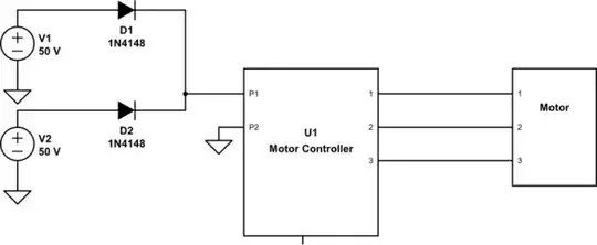
simulate this circuit – Schematic created using CircuitLab

The only thing I can think of is to get a TVS diode and size it correctly to stop any overvoltage, however, the event can happen multiple times at a fast rate. I have not measured it yet, but I suspect that it can happen up to 20Hz. Will a TVS diode be sufficient here? Is there a recovery period for a TVS diode is I guess what I am asking.

The other issue is my system power supplies that are connected on the same node as the motor controller can not handle more than 60V, and I couldn't find a TVS diode that has a working voltage of 50V but a voltage breakdown of anything lower than 60V.

J. Jones
  • 91
  • 6
  • what are the diodes in front of each battery for? – dandavis Jun 02 '20 at 21:56
  • @dandavis There is a requirement to not allow the batteries to charge each others. The real circuit actually has a smart diode with fets, however, for simplicity I just put diodes here. – J. Jones Jun 02 '20 at 22:03
  • 1
    The limitation will be thermal. Assuming the part is chosen correctly to handle 1strike, the part needs to dissipate the energy (or cool down) before the next threat appears. If the period between threats is too short, the internal temperature will start to staircase before it fails –  Jun 02 '20 at 22:20
  • TVS is (usually) designed for transient voltages lasting on the order of ns or us. You will typically see power ratings (like 40W or 3kW), and if you look at the datasheets these powers are for very short times, so the actual amount of energy dissipated isnt that big. Depending on the size of your motor, these energy levels may be way smaller than you need – BeB00 Jun 02 '20 at 22:56
  • @JonRB The other part of the question is choosing the correct TVS. From my understanding is a 50V working voltage of a TVS will only clamp at around 80V. It seems like that is too high for my system. – J. Jones Jun 02 '20 at 22:59
  • @BeB00 My pulse was actually closer to 500mS. Though I am not 100% confident on the number as I only took it once before I stopped my test. I do remember that my scope was at 250mS per division and the pulse lasted over 2 divisions. – J. Jones Jun 02 '20 at 23:03
  • TVS diodes do not have an inherent wear out mechanism, unlike MOVs. That doesn't mean you can't degrade them from hitting them too hard. This would be count as misusing them though. – DKNguyen Jun 02 '20 at 23:03
  • 250ms is a huge time, and not really suitable for a TVS. What power are you driving your motor at? Maybe you need more elegant power source switching – BeB00 Jun 02 '20 at 23:05
  • @BeB00 I have 4 motors in the system, each are at 50V 20-40A. Depending on the payload. – J. Jones Jun 02 '20 at 23:11
  • "when my motor breaks" did you mean "brakes"? If yes, then your battery is not "absorbing the overvoltage" it is recuperating, which is great feature to have. I'd rather replace the pair of batteries with one bigger battery than lose recuperation and create the problem you are trying to resolve here. – Maple Jun 02 '20 at 23:16
  • You need to dissipate 4kJ then, which is a massive amount of energy. It's enough to heat up 10g of silicon to >500C. Any reasonable TVS diode would probably melt. Having that energy go into charging batteries is much better than trying to turn it into heat. – BeB00 Jun 02 '20 at 23:20
  • @Maple Yes sorry brakes, Unfortunately, that is not an option. There aren't many 6 cell batteries that have the same energy density as ours 260Wh/KG. – J. Jones Jun 02 '20 at 23:22
  • @BeB00 I was afraid of that. I am wondering if I added a diode that goes back into the batteries and allow for a current path will help? Not sure if that will break my smart diode circuit that is supposed to handle the battery switching. – J. Jones Jun 02 '20 at 23:24
  • Yes, that will mess up your battery switching. Why do you need two packs? You should be able to get one custom pack that has the same characteristics as your two packs – BeB00 Jun 02 '20 at 23:39
  • "to not allow the batteries to charge each others" Do you realize that with your schematics you either have one battery working for two, or both of them working at the same voltage, which means they would not "charge each other" even connected directly? Is building 6S2P pack not an option? – Maple Jun 02 '20 at 23:43
  • 2
    Sounds like you need a braking resistor. This is a high power resistor that turns on when the bus voltage exceeds some threshold. Many VFD's have provision for attaching brake resistors. – user57037 Jun 03 '20 at 00:08
  • maybe all you need there is a large capacitor. – Jasen Слава Україні Jun 03 '20 at 09:38
  • 1
    @Jasen Someone upthread mentioned 4kJ. That would probably be too much to put in a capacitor. OP should look at the mechanical system kinetic energy and convert it to joules then calculate capacitor size and voltage rise to see if it is workable. – user57037 Jun 03 '20 at 19:04
  • have the mosfets used as diodes, driven in such as way as to always have one of the batteries connected. – Jasen Слава Україні Jun 03 '20 at 20:21

0 Answers0