For an ideal op-amp the voltages at the inputs are said to be of equal value ...
No. If negative feedback is applied and the output is not driven into saturation then the inputs will be very, very close to equal.
... and the currents 0, ...
Yes, due to the high and sometimes very, very high input impedance.
... however, for we also know that \$ V_{out}=A(V_p−V_n) \$
but if the voltages are the same the output should always be 0!
Correct. And that is why the voltages are not the same (but very, very close). The difference in voltages can be worked out by rearranging your formula to $$ V_p - V_n = \frac {V_{out}}{A} $$ and since A is very large the difference in inputs is very small - so small that it's almost zero.
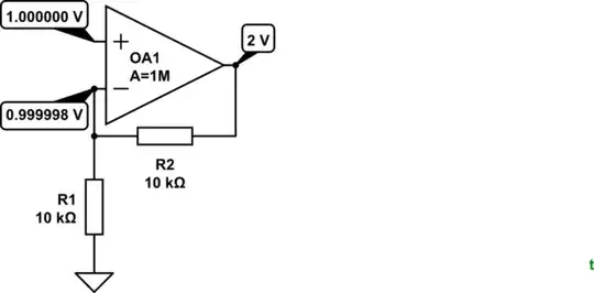
simulate this circuit – Schematic created using CircuitLab
Figure 1. Non-inverting amplifier with a gain of 2.
From the comments:
When analyzing an op-amp circuit with negative feedback assuming it is ideal we make the assumptions (almost in this order):
- Input voltages are the same;
Yes, but we know deep down that they are slightly different.
- The gain of the op-amp goes to infinity;
The gain of the op-amp is fixed as specified in the datasheet. 1M to 10M would be typical.
- Work out the output voltage and find out that the gain is finite and dependent of the circuit around the op-amp.
The gain of the complete circuit is "finite" (a modest value, say, of 1 to 1k) rather than the open-loop gain of 1M to 10M which hasn't changed, no matter what the feedback arrangement is.
If in a circuit the only thing that causes a gain is the op-amp then the gain of the circuit is the gain of the op-amp, so our reasoning appears to be flawed.
Nope. You're forgetting the negative feedback. This controls the overall circuit gain and corrects any variations and non-linearities in the op-amp itself.
I think I just got it, my problem now lies in "How" does the negative feedback controls the circuit gain, ...
Let's look at Figure 1 again.
- Initially Vp is at 0 V so the output and Vn are at 0 V too.
- VP is suddenly and instantly switched from 0 to +1 V.
- VP - Vn = 1 V so (since the open-loop gain of the op-amp itself is 1M) the output starts to swing towards +1,000,000 V at a rate limited by the slew rate of the op-amp.
- As it does, VP - Vn is decreasing and by the time Vout reaches 0.5 V, VP - Vn = 0.75 V so the output is now trying to swing to 750,000 V (but is still only at 0.5 V). Remember that the feedback is dividing by 2.
- This process continues so that as the output gets approaches 2.0 V the difference between the inputs is getting close to zero and so the target output voltage is falling too. The feedback is reducing the output drive and bringing it under control.
- Very quickly the output reaches 2.0 V and at this point Vn is just a millionth or two below 1 V and the circuit is stable, balanced, happy and under control.

