I am trying to come up with a device that can connect to 0-10V wall dimmer(sinking) and convert it to corresponding PWM signal. I have trouble understanding how the 0-10V interface has to be designed on the device to support 0-10V sinking dimmers. Please suggest a low cost option. Example circuit will be greatly appreciated.
Asked
Active
Viewed 1,017 times
2
-
See Switching circuit for driving LED at different current and Dimmable mains PSU control. – Transistor Nov 13 '18 at 18:21
-
Thanks for guiding me to those articles, but I am not sure how to supply the small current- constant current. And according to the dimming input circuit, can the Vdd signal be less than 10V to support 0-10V dimming signal. Please forgive my naivety. – Sudeep Dodda Nov 13 '18 at 18:38
-
In the linked examples the current source is built into the power supply. I don't know how your wall dimmers are designed. – Transistor Nov 13 '18 at 18:43
-
Low cost option would be to buy them, e.g. Mean well ELG. – tobalt Apr 29 '21 at 04:20
1 Answers
2
You really have two separate tasks and they are not related:
- How to drive a 0-10V dimmer and digitize the signal produced.
- How to produce a PWM signal based on a value sourced elsewhere.
To drive IEC 60929 annex e.2. dimmers you source current from the load device or you power them separately. The standard is 2mA maximum sink, but this varies device to device (load controller). This Tech note may help you understand.
Most 0-10V dimmer controls DO NOT produce a 0-10V signal, they typically produce a 0.5 or 1V low to a 10V high signal. The IEC standard says that at <= 1V the light would be off and at +> 9V the light would be 100%. For example. you can even just hook up a potentiometer to the 0-10V signal point and sink current to the Gnd and get a light to dim.
Now to your specific problem, You don't say if you have externally powered (typically a 12VDC supply) dimmers or not.
Assuming externally powered. then you just need to provide a current source and maximum voltage to the dimmer, and use a D/A to digitize the signal line.
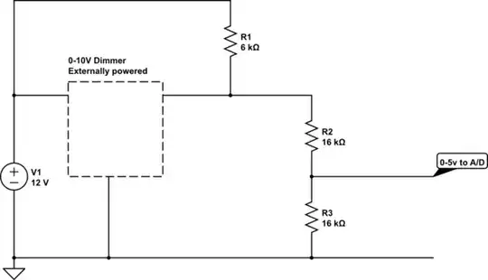
simulate this circuit – Schematic created using CircuitLab
Use something like an Arduino to digitize the dimmer signal, and produce the PWM signal you want.
Jack Creasey
- 21,729
- 2
- 15
- 29
-
Thank you for your thorough explanation. Yes this problem is two fold. The second part of converting analog to PWM will be handled by a 8-bit microcontroller (I am planning on using ATtiny 416/816). But my main concern is coming up with a circuit for the primary conversion. The dimmer I wish to use will be standard 0-10V sinking dimmer from Lutron (DVSTV-AL). It does not have it's own 0-12VDC power supply. But my driver has 0-12V supply which I can use to power my conversion device. Can you please help me figure out current source and max voltage with the given 12V aux supply from my driver. – Sudeep Dodda Nov 13 '18 at 20:03