1

I'm currently working on a project which requires me to test the functionality of TTL logic gates by making use of diodes and resistors. To do so I must first place them on the breadboard and then calculate their voltage with an electronic tester.

However I lack the skills and knowledge required to accomplish the task, since I don't know how to set up a breadboard, therefore I'm not only asking for a scheme but also, possibly, for some pointers related to the subject, in order to gain some knowledge about it.

Breadboard layout question doesn't cover how breadboards are built from circuits since it lacks any sort of examples, and it doesn't address the main issue, which would be coming up with a scheme for the circuits.

The following are the circuits I must build on the breadboard:

enter image description here

JRE
  • 71,321
  • 10
  • 107
  • 188
CloudZeta
  • 29
  • 6
  • 2
    Actually, the question you claim does not address this, does address this. What you appear to actually be stumbling over is the "blank sheet of paper" problem. You have countless choices which will work, and for the purposes of the simple tests you need to run, there's little to uniquely recommend any over the others. Though being neat and consistent has value. If you're really at a loss for ideas, there are countless examples available by web searching. Stack exchange sites exist for the specific problems that cannot be solved that way, rather than the problems which can. – Chris Stratton Sep 28 '18 at 15:25

2 Answers2

18

Breadboards are pretty easy to use. They look like this:

enter image description here

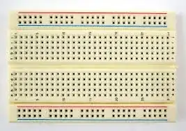
So to get a circuit to work in them, all you need to do is put the legs of the components in the holes. Now, to make your circuit work, you need to know how the holes are connected....

enter image description here

The top and bottom are generally where you would have your power rails (5V/12V/GND etc) and they are connected horizontally to each other (in the orientation of the picture)

The inner holes are connected to each other vertically (in the picture orientation). So, if you placed a wire from any hole on that red line (let's say this was at 5V), and connected it to any hole in section B or C (on the picture), then that column would now be at 5V.

Take a look at this example (taken from HERE which is also a good link to learn how to use breadboards):

enter image description here

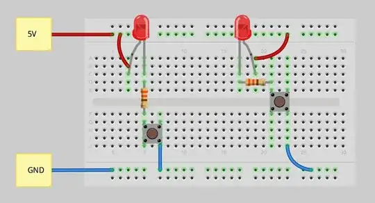
Each row or column highlighted GREEN is connected. You see how the red wires from the 5V rail is able to power the LED? The Anode could be placed in any hole on that vertical line and the circuit would still work.

Be careful with the breadboard you have. Some of them don't always have the power rails connected all the way across. One such breadboard can be seen here:

enter image description here

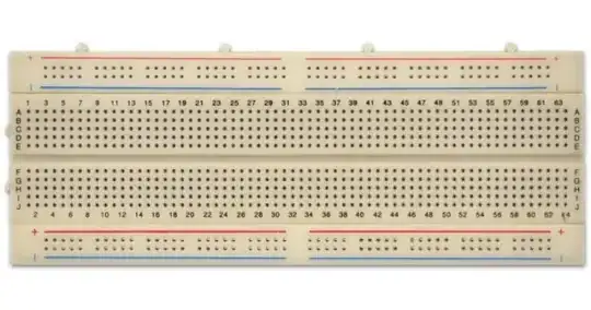
Luckily, with this type, it indicates that the power rails do not go all the way across. You can tell that where the red and blue lines have a break, the connection breaks. You would have to place a wire between each side to ensure the power rails are connected. Some cheaper breadboards don't have these indicators, so it is always a good idea to check the rails. A simple way to do it is just place a bit of wire in each side and check continuity.

Breadboard graphics found at:

https://www.tweaking4all.com/hardware/breadboard/

https://moderndevice.com/product/medium-size-breadboard-320-hole-1x/

https://potentiallabs.com/cart/buy-breadboard-850-points-online-hyderabad

MCG
  • 11,923
  • 5
  • 35
  • 71
  • Thanks, that's pretty much the information I needed! Do you know any programs that I could use to practice? – CloudZeta Sep 28 '18 at 15:33
  • 2
    The only one I know of to do breadboard layouts is Fritzing. It's the program used for my last picture – MCG Sep 28 '18 at 15:46
  • Not a big fan of Fritzing but you managed to make it look nice so +1 for you :) –  Sep 28 '18 at 15:56
  • @KingDuken I'm not a fan either, that was a picture taken from the site I linked, I didn't actually do it. But it's obvious which program was used! – MCG Sep 28 '18 at 16:00
  • 4
    A heads up, some breadboards break the power busses (going along the top and bottom) at the midpoint. So for example if you wire in power at the top right, it is only connected as far as the middle, and doesn't go as far as the top left. My first breadboard did this and was not clearly marked... – 1N4007 Sep 28 '18 at 16:10
  • The ones with red and blue lines are marked, but he blank ones are not unfortunately. I'd edit in an example, but I'm on my phone at the moment! – MCG Sep 28 '18 at 16:12
  • A lot of cheap ones do not have the rails all the way through and the gaps are not conneczed – PlasmaHH Sep 28 '18 at 16:27
  • When I get back to the computer, I'll update this answer with an example of one without rails all the way through. Unless anyone else would like to? – MCG Sep 28 '18 at 16:34
  • Where did you find the second graphic? I'd like to use it but source it. – Bergi Sep 28 '18 at 16:44
  • I'll update the answer with links – MCG Sep 28 '18 at 16:49
1

Regarding your example circuits (3) not related to the accepted answer;

(1) is best for TTL with greater Iol ( low level output current replacing ground with TTL output. Read specsheet Vol and divide by Iol to compute = "Rol" as the logic driver's resistance . This is an internal equivalent resistance from Ohm's Law as a general rule of thumb. (5V-Voh)/Ioh=Roh

(2) won't work with 0V on each side

(3) will be dim if driven by TTL on +5V side but brighter if drive from Gnd (=0V) side "Rol and Roh" are my terms and not found in datasheets but for your understand of the rise in voltage with current on the low voltage output.

CMOS is more symmetrical 50 to 25 Ohms for 5V and 3V logic respectively.
TTL is designed for >2V at much lower currents and is higher impedance than CMOS for "Roh" so it may not drive a LED from the high side but easily from the low side.

You should measure current from the voltage drop on your current limiting R and compare with Vf or forward voltage drop on LED (diode) to get familiar with how Ohm's Law works and nonlinear effects of diodes from Vf vs log(I) when forward biased.

Tony Stewart EE75
  • 1
  • 3
  • 54
  • 185
  • 1
    This is a relatively decent answer. However, look at the question. OP is clearly a beginner and this is likely to go way over their head. – MCG Sep 28 '18 at 16:02
  • Ohm's Law is fundamental to learn and LED's are a good start as well as characterstics for resistance or current limits on different logic families. – Tony Stewart EE75 Sep 28 '18 at 17:13
  • 1
    Yeah I agree. It's the wording of it. It's not an answer suitable for beginners which OP clearly is. I'm not saying it's a bad answer, I'm saying it's not going to be helpful to OP. Although that being said, it doesn't actually address the question asked which was about using breadboards. – MCG Sep 28 '18 at 17:21
  • It was directed to similar users of varying skills learning. I started with the statement saying not related (intended for) to be an answer but ( still relevant to examples given)... Not the OP who already accepted an answer but is at the initial breadboard stage. FWIW I understand. Sometimes learners don't know what questions to ask. – Tony Stewart EE75 Sep 28 '18 at 17:40
  • 1
    I don't understand why you would answer a question but not direct it at the person asking? I think some simplifying and explaining in layman's terms will go a long way to direct it at people with varying skill levels, and be useful to OP and other beginners who may come across this question – MCG Sep 28 '18 at 17:43
  • I answer for a wider audience ( the thrust of this forum) and hopefully the OP grasps something of it as well. Some may find it useful even if tangential to the question but relevant to the schematics shown. Some slower learners may not appreciate that those who need to know the next gotcha thing about the schematic. I call it outside the box thinking and I realize some do not appreciate it. It is not different than warning someone about high voltage when they ask about placing a filter cap from line and gnd. even if the direct question was already asked. This site is not a Quora or Wiki site – Tony Stewart EE75 Sep 28 '18 at 17:51