Here is how experimentalists at diyaudio.com achieved low-nanovolt gnd-trash levels needed for 100 dB dynamic range and SNR, for vinyl record playback using moving-coil cartridges with 100 microvolt output levels.
simulate this circuit – Schematic created using CircuitLab
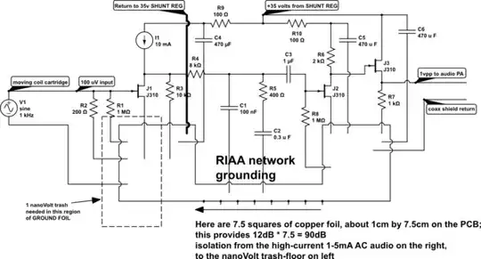
Notice the THREE regions of this GROUND PLANE:
LEFT region for the first JFET, a lownoise device, and all the input terminations and coax shield and bypass caps for the VDD (heavy R+C filtering);
CENTRAL region with two purposes
.... (1) grounds for the RIAA frequency compensation [50Hz pole, 500Hz zero, at voltage levels 30dB (31X) higher than from the movingcoil cartridge],
.... (2) the attenuation, IN THE NARROW REGION of the GROUND PLANE, of currents that might circulate between the PowerAmplifier coax shield-return and bottom of C6. This output signal current --- 1 mA --- times 1 mohm, produces 1 uV of ground voltage GRADIENT. This gradient may occur only on the right side of the PCB near the pulldown R7 of the output buffer JFET;
RIGHT region, where high ground currents flow (1 mA signal current to and from the power amplifier) and from the two 470 uF bypass caps on the 35 volt rail. These currents must have a DC path to/from the first gain stage, but AC currents must be strongly attenuated.
The long thin central region provides that attenuation.
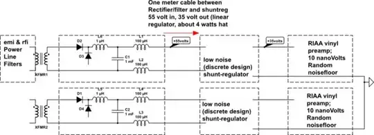
BUT MORE WAS DONE. Here is how those two PCBs (audio Left and RIGHT) were powered.
simulate this circuit
