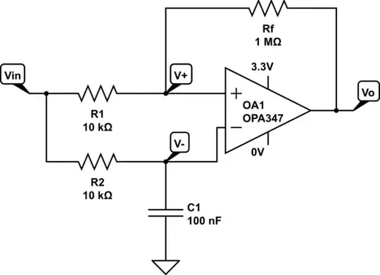
This is a follow-up from here. I have got the following Schmitt trigger circuit implemented already on a breadboard. As seen, the input signal at the non-inverting and inverting terminals of the op amp is the same, but with the addition of a RC circuit in the inverting terminal. In this way, I am comparing the input signal with a delayed version of the same signal such that I can identify peaks.
simulate this circuit – Schematic created using CircuitLab
What I am trying to do now is to analytically obtain the hysteresis of the circuit. I have done so using the superposition theorem, but I am not sure of whether the result is right, and if so, how I can apply it.
I followed a similar procedure as in here:
The output voltage of the circuit, \$V_o\$, is given by: \begin{equation} V_{o} = A_{v}(V^{+} + V^{-}) \end{equation} where \$V^+\$ and \$V^-\$ are the voltages at the non-inverting and inverting terminals, and \$A_v\$ is the circuit's gain. This gain is: \begin{equation} V_{+} = \dfrac{V_{OH} - V_{OL}}{V_{IH} - V_{IL}} \end{equation} where \$V_{IH}\$ is the smallest voltage at which the output voltage is \$V_{OL}\$, while \$V_{IL}\$ is the largest input voltage at which the output voltage is \$V_{OH}\$.
The voltage \$V^{+}\$ is: \begin{equation} V_{+} = V_{in}\dfrac{R_{f}}{R_{1} + R_{f}} + V_{o}\dfrac{R_{1}}{R_{1} + R_{f}} \end{equation}
The voltage \$V^{-}\$ (it is from here where I start doubting) is actually the voltage accross the capacitor \$C^{1}\$: \begin{equation} V^{-} = V_{in}(1-e^{-t/R_{2}C_{1}}) \end{equation}
If we assume the initial state of \$V_{o}\$ is \$V_{OH}\$ then: \begin{equation} V_{+} = V_{in}\dfrac{R_{f}}{R_{1} + R_{f}} + V_{OH}\dfrac{R_{1}}{R_{1} + R_{f}} \end{equation}
and the output is:
\begin{equation} V_{o} = A_{v}\bigg[V_{OH}\dfrac{R_{1}}{R_{1} + R_{f}} - V_{in}\bigg(1 - \dfrac{R_{f}}{R_{1} + R_{f}} - e^{-t/R_{2}C_{1}}\bigg)\bigg] \end{equation}
So from the previous equation one can see that the output will remain at \$V_{OH}\$ as long as: \begin{equation} V_{OH}\dfrac{R_{1}}{R_{1} + R_{f}} > V_{in}\bigg(1 - \dfrac{R_{f}}{R_{1} + R_{f}} - e^{-t/R_{2}C_{1}}\bigg) \end{equation}
or
\begin{equation} V_{OH}\dfrac{R_{1}}{R_{1} - (R_{1} + R_{f})e^{-t/R_{2}C_{1}} } > V_{in} \end{equation}
and the transition from \$V_{OH}\$ to \$V_{OL}\$ will happen when \$V_{OH}\$ as long as: \begin{equation} V_{in} > V_{IL} \equiv V_{OH}\dfrac{R_{1}}{R_{1} - (R_{1} + R_{f})e^{-t/R_{2}C_{1}} } \end{equation}
If we follow a similar procedure, we find that \begin{equation} V_{IH} \equiv V_{OL}\dfrac{R_{1}}{R_{1} - (R_{1} + R_{f})e^{-t/R_{2}C_{1}} } \end{equation}
And that the hysteresis is:
\begin{equation} V_{Hysteresis}=V_{IL} - V_{IH}=(V_{OH} - V_{OL})\dfrac{R_{1}}{R_{1} - (R_{1} + R_{f})e^{-t/R_{2}C_{1}} } \end{equation}
Does all of this make a degree of sense? If so, because of the exponential term, I cannot see how to proceed from here to obtain a measurable value of the hysteresis (e.g., everything beyond some voltage threshold value triggers a transition. What is this voltage threshold value?) I have seen that modifying the resistors \$R_{1}\$ and \$R_{f}\$ allows me to pass higher or lower input voltages, but then at some point I need to change the values of \$R_{2}\$ and \$C_{1}\$ as otherwise I see nothing in the output. How can I relate all of this to the math (or even simulation)?
Any help is much appreciated. Thanks.
What I have seen is that by varying R1 and/or Rf, minimum voltage amplitude of the input signal to trigger a change in the circuit's output either increases or decreases (depending on the values of these resistors) so I believe there may be some equation that tells me what this minimum value is. I just don't know how to derive it.
Thanks by the way :)
– sigur_ros May 31 '18 at 16:05Thanks again to all of you
– sigur_ros May 31 '18 at 17:29