-3

According to my very basic understanding of Electrical Circuits, the P.D. across a wire with no resistance is sometimes zero.

Take this question for example: "If voltage is measured between two points on a wire, with no resistance in between is the voltage zero?"

From what I can see, the reason why the potential difference of a wire is 0 is because the voltage at the two points on the wire are the same. Thus, they have a difference of 0V and hence, the P.D is 0. (Please clarify if I have misunderstood)

Can I say that in other words, as V=RI, and R=0, so V=0?

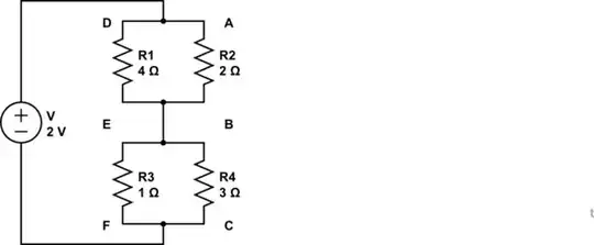
So here is my question. In the figure below, what would be the P.D. of the wire BE?

enter image description here Suppose that the EMF of the battery is 2V. And the resistance of the wire is negligible.

So I can come to 2 possible conclusions: The P.D. is either 0 or -0.8 or it could be neither

I could be 0. V=RI and as the wire has technically no resistance, therefore, the P.D. has to be 0.

Or it could be -0.8V. Voltage at point A and D is both 2V as voltage splits evenly in parallel circuits regardless of resistance. Using the formula:

PD[a]=[R[a]/(R[a]+R[b])] x V

The P.D of the 2Ω resistor is 0.8V and hence the P.D at B is 0.8V(Or should it be 1.2V?) The P.D of the 4Ω resistor is 1.6V and hence the P.D at E is 1.6V(Or should it be 0.4V?)

Therefore, taking 0.8(P.D at B)-1.6(P.D at E) = -0.8

Is my workings correct? Or is my understanding of Voltage flawed. (which it probably is) Please clarify and include an answer to the above question if possible.

David Toh
  • 97
  • 3
  • 1
    Always, except for infinite current. –  Feb 07 '16 at 17:11
  • @BrianDrummond Does that mean that the P.D. of BE should be 0? – David Toh Feb 07 '16 at 17:13
  • 3
    Follow the implications of the above comment. –  Feb 07 '16 at 17:14
  • 1
    @BrianDrummond That would mean that my answer of -0.8 is wrong i suppose. What if I connected voltmeter IN SERIES to the wire BE. Would it read -0.8V? Because then I would be calculating the difference in the voltage at points B and E. – David Toh Feb 07 '16 at 17:20
  • For theoretical wires, the resistance is zero, so there can be no voltage between points along a theoretical wire. The problem states that the resistance of the wire is negligible, so the voltage between points B and E will also be negligible. – Peter Bennett Feb 07 '16 at 17:20
  • If you are connecting the voltmeter in series you are modifying the circuit and anything you measure is irrelevant to this circuit. –  Feb 07 '16 at 17:21
  • What does a Partial Derivative across a wire even mean? – Olin Lathrop Feb 07 '16 at 17:23
  • 3
    PD = Potential Difference ... the use of initial definitions should be enforced at gun point.... – Spoon Feb 07 '16 at 17:54

1 Answers1

4

Lets redraw the schematic:

schematic

simulate this circuit – Schematic created using CircuitLab

Circuit diagrams are topological meaning that the "wires" do not really exist, they merely indicate what is connected to what (essentially they are ideal and 0 Ohms). The circuit above is exactly the same circuit as you have shown, but it should make thinks much clearer.

Notice how R1 and R2 (labels given in my diagram) are in parallel. Also R3 and R4 are in parallel.

The total resistance for parallel resistors is given by:

$$\frac{1}{R_t} = \frac{1}{R_1} + \frac{1}{R_2} + \frac{1}{R_3} + ...$$

For two parallel resistors, this simplifies to:

$$ R_t = \frac{R_1 R_2}{R_1 + R_2}$$

So you can find the total resistance of the two parallel branches, and then use the simple voltage divider equation (below) to work out what the voltage drop of each resistor must be.

$$ V_{mid} = V_{sup} \times \frac{R_{bot}}{R_{bot}+R_{top}}$$


As a side note, P.D is not a very well know acronym, and quite ambiguous. When I first read the question it took a moment to work out what you were talking about - was it power dissipation? potential difference (voltage)? or something else.

Furthermore, you can't have a potential difference at one point (well you can but it is always zero). You can have a potential difference between two different points. So saying "(P.D at B)" is nonsense.

Tom Carpenter
  • 65,995
  • 3
  • 145
  • 204
  • SO what the wire BE did essentially was to alter the arrangement of the circuit? Instead of the total resistance being 2.5Ω(Without BE). It is now 2.08Ω. – David Toh Feb 07 '16 at 17:30
  • @DavidToh without the connection, the $V_{EF}$ (voltage at E relative to F) and $V_{BC}$ Will be different because the resistors have a different ratio. However in connecting the wire, you force those two points be at the same voltage which in turn changes the current through the circuit (and so the total resistance). – Tom Carpenter Feb 07 '16 at 17:35