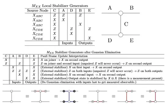
So, in order to clarify what I wrote in the comments I'll write an answer here. I found a convincing approach by adding variables to nodes and combining it to ZX-Calculus with scalars (scalars are like normalization factors, see for example this paper). Indeed, a red node labelled with $0$ means "project on 0" and the red node labeled with $\pi$ means "project on $1$". That way, I can write directly a red node labelled $a\pi$, which is equivalent to saying that I measured an $a$.
This approach is equivalent to writing two diagrams, one with a red node $0$ and one with a red node $\pi$, and rewrite it until you get simple scalars (that's why you need ZX-Calculus with scalars), and this scalar will be equal to the probability of measuring $0$ or $1$. The addition of variables is just a nice trick to make sure that you just write a single diagram, which is much quicker to write, especially when you add several measurements. This idea is used (introduced?) for example in this paper. Note however that you need to extend the rules a bit, in order to add rules that apply for nodes with variables. But usually it's not very hard to see which rule you need to apply: just see for each rule what happens when $a=0$ and when $a=1$, and here you go!
This approach is so great that now I never write any matrix to check math statements/circuits/...: I just write a small ZX diagram, and I can check what happens very easily!
Sorry, I don't have time right now to give examples, but I'm planning to write a blog post at some point... Will come back when I do so. In the meantime, feel free to ask questions in comments!
