1

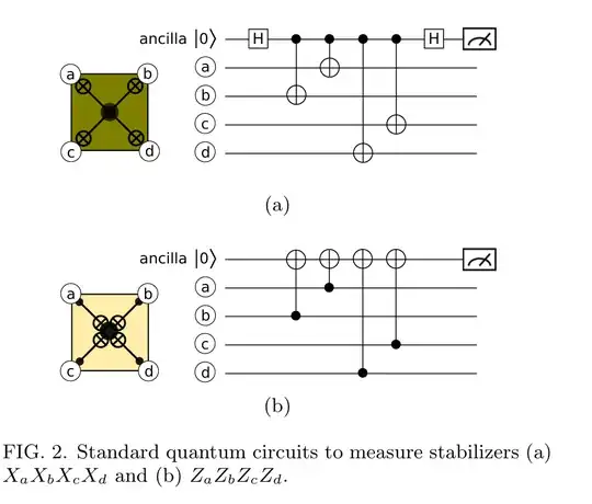
I am trying to measure stabilizers in a surface code, a common circuit to measure stabilizers look like this: https://arxiv.org/pdf/1404.3747

Fig 2a from paper  https://arxiv.org/pdf/1404.3747

The problem is when Measuring the X-stabilizer circuits in Qiskit (python). It returns nothing useful. Take the following code snippet which implement fig 2a's circuit:

ar_z = QuantumRegister(1, 'ar_z')
cr_z = ClassicalRegister(1, 'cr_z')
dr = QuantumRegister(4, 'd')
qc = QuantumCircuit(ar_z,dr, cr_z)

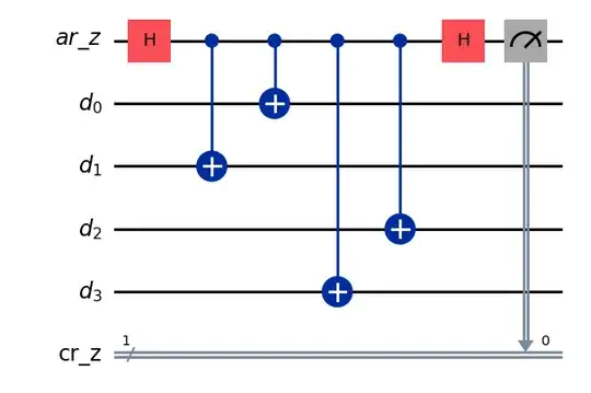
qc.h(ar_z[0]) qc.cx(ar_z[0], dr[1]) qc.cx(ar_z[0], dr[0]) qc.cx(ar_z[0], dr[3]) qc.cx(ar_z[0], dr[2]) qc.h(ar_z[0])

qc.measure(ar_z, cr_z)

simulator = AerSimulator() result = simulator.run(qc).result() print(result.get_counts())

qc.draw(output='mpl') plt.show()

Drawing the output:

Circuit output from mpl

And the resutls: {'1': 536, '0': 488}

This tells me nothing useful about the ancilla or weather an error was induced on one of the data qubits. My thoughts was that if a z-error was induced on one of the qubits, the ancilla would return 1? else 0. Is this not the case? if so How do I measure the X-stabilizers?
ikky
  • 13
  • 3

1 Answers1

2

You're not measuring a stabilizer here (not in the sense that your measurement is supposed to be deterministic), because your register $d$ starts in the $|0\rangle^{\otimes 4}$ quantum state and not a valid logical quantum state.

Before the measurement can be observed as deterministic, you have to project $d$ into the codespace. This can be done with an encoding circuit, or by first measuring all the code stabilizers once.

You observe a 50%/50% repartition, just as if you measured the state $|0\rangle$ in the $X$ basis for the first time. Note that $Z$-stabilizers already stabilize the $|0\rangle^{\otimes n}$ state, so it is only necessary to measure the $X$-stabilizers once to project the register into the codespace.

Consider the following circuit:

from qiskit import QuantumRegister, ClassicalRegister, QuantumCircuit
from qiskit_aer import AerSimulator

import matplotlib.pyplot as plt

ar_z = QuantumRegister(2, 'ar_z') cr_z = ClassicalRegister(2, 'cr_z') dr = QuantumRegister(4, 'd') qc = QuantumCircuit(ar_z,dr, cr_z)

qc.h(ar_z[0]) qc.cx(ar_z[0], dr[1]) qc.cx(ar_z[0], dr[0]) qc.cx(ar_z[0], dr[3]) qc.cx(ar_z[0], dr[2]) qc.h(ar_z[0])

qc.z(dr[1]) # Uncomment to add Pauli error and see changes

qc.h(ar_z[1]) qc.cx(ar_z[1], dr[1]) qc.cx(ar_z[1], dr[0]) qc.cx(ar_z[1], dr[3]) qc.cx(ar_z[1], dr[2]) qc.h(ar_z[1])

qc.measure(ar_z, cr_z)

simulator = AerSimulator() result = simulator.run(qc).result() print(result.get_counts())

qc.draw(output='mpl') plt.show()

It repeats your measurement protocol, and you can check that the $X$-stabilizer measurements are now deterministic starting from the second. Adding a $Z$ Pauli error in-between the two measurements indeed flips the second measurement, so it successfully detects a Pauli $Z$ error.

In a true simulation, you do not want to add the $Z$ errors manually, but to rely on the simulator to randomly add noise according to a defined noise model.

Peter-Jan
  • 2,163
  • 8
  • 28
AG47
  • 1,575
  • 3
  • 16