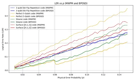
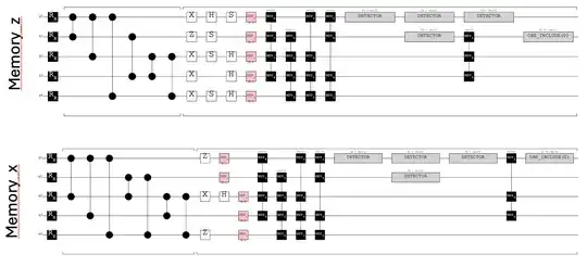
I'm plotting logical error rates for different codes and comparing two decoders (BP-OSD and MWPM)  For each code I calculate logical error rates by preparing the code in $|0\rangle_L$ state with encoding circuit ($p_{L_0}$), measuring stabilizers and measuring logical $Z$ and preparing the code in $|+\rangle_L$ state, measuring stabilizers and measuring logical $X$ ($p_{L_+}$). Then what's plotted here is $p_{L} = p_{L_0} + p_{L_+}$. Here are the example circuits I would use for estimating $p_L$ of 5-qubit code:
 Let me know if these circuits look right to you. I know normally one does several rounds on syndrome measurements but I'm only interested in comparing capabilities of the codes so I'm hoping one round of syndrome measurements should suffice. For clarity here are the same circuits but presented differently
circ_mem_z = stim.Circuit('''RX 0 1 2 3 4
TICK
CZ 0 1 0 2 0 4 1 3 2 3 2 4
TICK
X 0 2 3 4
Z 1
S 1 2 4
H 0 2 3 4
S 0
DEPOLARIZE1(0.1) 0 1 2 3 4
MPP X0*Z1*Z2*X3 X1*Z2*Z3*X4 X0*X2*Z3*Z4 Z0*X1*X3*Z4
DETECTOR rec[-1]
DETECTOR rec[-2]
DETECTOR rec[-3]
DETECTOR rec[-4]
MPP Z1*X2*Z3
OBSERVABLE_INCLUDE(0) rec[-1]''')
circ_mem_x = stim.Circuit('''
RX 0 1 2 3 4
TICK
CZ 0 2 0 3 0 4 1 2 1 4 2 3 2 4
TICK
X 2
Z 0 4
H 2
DEPOLARIZE1(0.1) 0 1 2 3 4
MPP X0Z1Z2X3 X1Z2Z3X4 X0X2Z3Z4 Z0X1X3Z4
DETECTOR rec[-1]
DETECTOR rec[-2]
DETECTOR rec[-3]
DETECTOR rec[-4]
MPP Z0X2X3
OBSERVABLE_INCLUDE(0) rec[-1]''')
