I'm learning surface code and lattice surgery based on "Surface code quantum computing by lattice surgery" and "Surface codes: Towards practical large-scale quantum computation", and trying to implement a logical S gate using stim
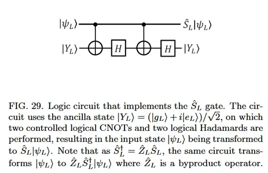
According to Fig. 29 in "Surface codes: Towards practical large-scale quantum computation". A logical S gate is implemented as
Then I tried to implement it using Stim based on lattice surgery step by step.
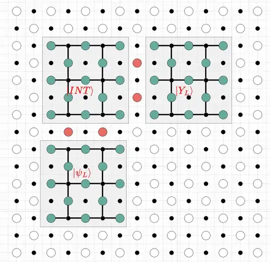
I assumed a layout after applying the first logical CNOT as below (similar to Fig. 7 in "Surface code quantum computing by lattice surgery")
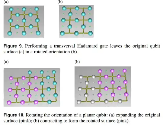
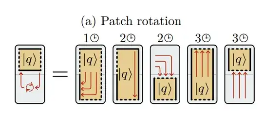
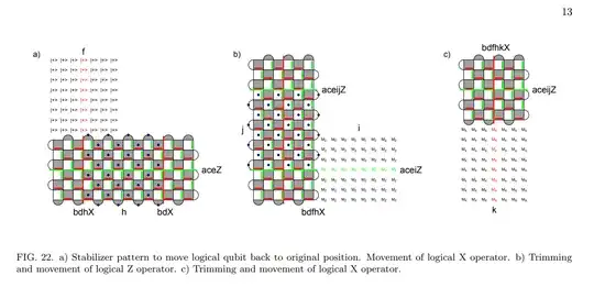
After applying the first H gate on $|Y_L\rangle$, the orientation of the corresponding surface changed and I followed Fig. 9 and Fig. 10 in "Surface code quantum computing by lattice surgery" to rotate it back to its original orientation
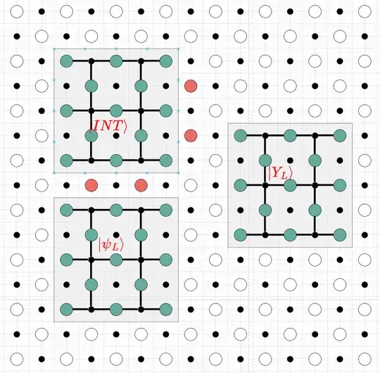
Then the layout became
My question is: How could I implement the second logical CNOT between $|\psi_L\rangle$ and $|Y_L\rangle$ given that the position of $|Y_L\rangle$ has changed?
