I am interested in Steane error correction (not to be confused with the Steane code). This is described in Fig. 1 of this paper.
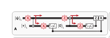
The idea is to create a $\vert +\rangle_L$ state with as many registers as used by $\vert\psi\rangle_L$ and connecting each data register to the ancilla with CNOTs. Finally, one measures the ancilla qubits. In the text, it says
This Steane-type QEC is to be seen in contrast to measuring each stabilizer individually, where due to fault tolerance requirements one has to resort to either verified Greenberger–Horne–Zeilinger (GHZ) states or flag schemes for the auxiliary qubits
I'm not really sure how this works.
Suppose I encode $\vert\psi\rangle_L$ into a CSS code (say the Steane code or the surface code). In the non-FT version (where I assume ancilla measurements are reliable and ancilla qubits don't have errors), I measure each stabilizer with an ancilla qubit. If some of them are $-1$, then I know an error occured. I work out which physical qubits to flip based on these.
I am struggling to understand how the error correction code works together with the Steane-type fault tolerance circuit shown.
- Why does measuring the $\vert +\rangle_L$ state in $Z$ basis (left half of figure) give us the correction $X_i$?
- How do I use the ancilla measurments of the figure for decoding? The figure suggests that I can simply correct any individual $X_j$ or $Z_i$ physical error on the data qubits after measuring the ancilla.
- Do I even measure the stabilizers of the code used to encode $\vert\psi\rangle_L$ at any point? Or is that information contained in the ancilla measurements?
Any pointers on how the overall scheme works would be greatly appreciated.