3

I'm trying to understand the circuit from Appendix A of the paper Fault-Tolerant One-Bit Addition with the Smallest Interesting Colour Code.

enter image description here

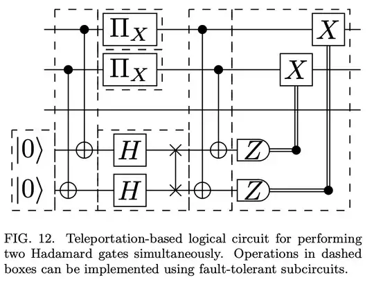
Here the top 3 qubits represent the 3 logical qubits of the $[[8,3,2]]$ color code (i'll call $|\psi\rangle$) and the bottom two are the two logical qubits of the $[[4,2,2]]$ code (I'll call $|\phi\rangle$). The problem being solved here is that there is no transversal Hadamard gate on the $[[8,3,2]]$, but there is on the $[[4,2,2]]$ code. So this circuit projects two qubits from $\psi$ onto $\phi$ using transversal CNOT, performs transversal Hadamard on $\phi$, and then teleports them back to $\psi$.

If anyone can provide a systematic explanation of how this circuit works, especially what the purpose of the logical $X$ measurements $\Pi_X$ and why the measurement controlled $X$ operators are done as they are that would be of great help.

The parts that are already clear to me are that performing Hadamard on the $[[4,2,2]]$ code is transversal (with a trivial swap) and there exist transversal CNOT gates between any two qubits of $\psi$ to $\phi$.

Recommendations for other sources to help understand these teleportation-type circuits would also be appreciated.

Thanks
tbg
  • 31
  • 2

1 Answers1

2

It's going to be easier to explain if we start with one qubit being teleported. I'm also going to use Gottesman-Knill to do the proofs here, and if you're not familiar with it, you should definitely read Chapters 1-6 of Daniel Gottesman's book, Chapter 6 deals with Gottesman-Knill, but the rest is just as necessary for people working in QEC.

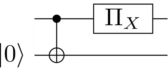
Let's take a look at a simplified version of the circuit above in stages. First, the teleportation: One-bit teleportation circuit

The system begins in a state with one stabilizer (because the bottom qubit is prepared in the zero state) and two logical operators which 'live on' the top qubit: \begin{equation} S = \begin{array}{cc} I & Z \\ \hline X & I \\ Z & I \end{array} \end{equation} Carrying out the CNot results in \begin{equation} S = \begin{array}{cc} Z & Z \\ \hline X & X \\ Z & I \end{array} \sim \begin{array}{cc} Z & Z \\ \hline X & X \\ I & Z \end{array}, \end{equation} then projecting the top qubit into the +1 eigenstate of $X$ gives us \begin{equation} \begin{array}{cc} X & I \\ \hline X & X \\ I & Z \end{array} \sim \begin{array}{cc} X & I \\ \hline I & X \\ I & Z \end{array}. \end{equation} The logical operators now live on the bottom qubit, and the top qubit is in a fixed state, so we've teleported the state from top to bottom with this gadget.

We had to use a different circuit to teleport the state back after the Hadamard, because the transversal CNot between the two code blocks only works if logical qubits of the $\left[\hspace{-2pt}\left[ 8,\, 3,\, 2 \right]\hspace{-2pt}\right]$ code are the control qubits: Alternative one-bit teleportation circuit

If you replicate the proof for this circuit, you'll see that the measurement may result in a state stabilized by $-IZ$ instead of $IZ$, so multiplying by the $ZZ$ logical operator would result in $-ZI$ instead of $ZI$ like we're after (this also happens in the first teleportation circuit, but is less important, so I just drew a projector instead of a measurement there). That's the reason the conditional $X$ is there.

Ben Criger
  • 93
  • 4