5

A comment (by Marcus Heinrich) in a previous post says :

"any stabiliser state is locally Clifford equivalent to a graph state and vice versa".

I can go from a graph (defined by its adjacency matrix) to a set of stabilizers and the corresponding state. My question is for the other direction : if I have a set of stabilizers that define a $[[n,0,d]]$ code; is there a procedure to get an adjacency matrix that would correspond to it?

unknown
  • 2,405
  • 1
  • 8
  • 21

2 Answers2

3

See this paper for a proof, but I will sumamrize the idea below.

Suppose you have a stabilizer state $|\psi\rangle$ and a set $\mathcal{S}$ of Paulis that generate its stabilizer group, $\langle S \rangle$.

You can represent the generators by a pair of matrices, $X$ and $Z$, such that $X[i, j] = 1$ if the $i$-th generator has a tensor factor of $\sigma_x$ in the $j$-th position.

For example, if you have generators $\sigma_x \otimes \sigma_x$ and $\sigma_z \otimes \sigma_z$ for the bell state, then the matrix you obtain is $X = \begin{pmatrix} 1 & 1 \\ 0 & 0 \end{pmatrix}$ and $Z = \begin{pmatrix} 0 & 0 \\ 1 & 1\end{pmatrix}$. Of course, you can always choose different generators, so this depiction is not unique.

If you do this procedure for a graph state $|G\rangle$ by using the natural generators of the stabilizer group of the graph state, you always obtain matrices where $X$ is identity, and $Z$ is exactly the adjacency matrix of the graph.

The claim now is: We can take any two matrices $X$ and $Z$ that encode a stabilizer group, and transform them into $X = I$ and $Z$ into a adjacency matrix.

This is done using something similar to a binary RREF procedure, where the binary addition of two rows is like multiplying two group generators to form a new group generator, or by swapping columns of the two matrix via conjugation by $H$ gate. This way, we can reduce $X$ matrix, obtaining identity, and it can be shown that $Z$ becomes symmetric. There are some additional details, but due to the structure of the matrices, we can always obtain an $X$ and $Z$ of this form.
xzkxyz
  • 606
  • 3
  • 3
3

You can use Stim to turn a stabilizer state into a graph state. Internally what it does is to decompose the stabilizer state into any circuit (it happens to do this by Gaussian elimination of the stabilizer tableau), then it feeds that circuit through a graph state simulator (relevant source code in stim), then it outputs the graph state as a circuit which has an RX layer followed by a CZ layer followed by a single qubit rotation layer.

For example, if you pick an arbitrary stabilizer state:

import stim

stabilizer_state = stim.Tableau.random(10) for stabilizer in stabilizer_state.to_stabilizers(): print("stabilizer", stabilizer)

prints (for example):

stabilizer +XXY__XYZYZ

stabilizer -ZZ___YX___

stabilizer -_XXZX_YYXY

stabilizer -__XXX_XY_Y

stabilizer +XX__YY__XZ

stabilizer +YZ_X_Z_Z_X

stabilizer +XXZX_XZYZ_

stabilizer -YYZYYYX_XZ

stabilizer -XZZXXZX_YZ

stabilizer +__Z_Z_XXZZ

You can get the graph state circuit for it:

graph_state_circuit = stabilizer_state.to_circuit("graph_state")
print(graph_state_circuit.diagram())
# prints (for example):
#         /-------------------------------------------\ /-----\
# q0: -RX-@-@-@-@-@-@-----------------------------------Z-H-----
#         | | | | | |
# q1: -RX-@-|-|-|-|-|-@-@-@-----------------------------S-H-----
#           | | | | | | | |
# q2: -RX---@-|-|-|-|-@-|-|-@-@-------------------------Z-H-----
#             | | | |   | | | |
# q3: -RX-----@-|-|-|---@-|-|-|-@-@-@---------------------H-----
#               | | |     | | | | | |
# q4: -RX-------|-|-|-----@-@-|-@-|-|-@-@-@-@-----------Z-H-----
#               | | |         |   | | | | | |
# q5: -RX-------|-|-|---------|---@-|-|-|-|-|-@-@---------H-----
#               | | |         |     | | | | | | |
# q6: -RX-------@-|-|---------|-----@-@-|-|-|-@-|-@-----X-S-H-S-
#                 | |         |         | | |   | |
# q7: -RX---------|-|---------|---------@-|-|---|-|-@-@-X---H---
#                 | |         |           | |   | | | |
# q8: -RX---------@-|---------|-----------@-|---|-@-@-|-X---H---
#                   |         |             |   |     |
# q9: -RX-----------@---------@-------------@---@-----@-Y---H---
#         \-------------------------------------------/ \-----/

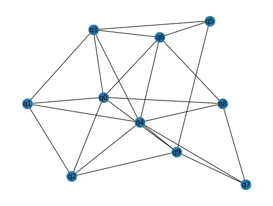
Once you have the circuit, it's quite easy to get the graph into a more normal format such as networkx:

import networkx as nx
graph = nx.Graph()
for instruction in graph_state_circuit:
    if instruction.name == 'CZ':
        targets = instruction.targets_copy()
        for a, b in zip(targets[::2], targets[1::2]):
            graph.add_edge(a.value, b.value)
nx.draw(graph, labels={k: f'q{k}' for k in graph.nodes})
# draws (for example):

enter image description here

Craig Gidney
  • 44,299
  • 1
  • 41
  • 116