When using a simulator, indeed it is possible to keep track on several things that evolves with the circuit. I find that keeping a track of the quantum statevector of the system and the unitary operator of the circuit are the most important ones. Here is an example of a simple code that tracks the statevector and unitary operator of a simple circuit:
from qiskit import QuantumCircuit
from qiskit.visualization import array_to_latex
from qiskit.quantum_info import Operator, Statevector
qc = QuantumCircuit(2)
qc.h(qc.qubits)
u1 = Operator(qc)
psi1 = Statevector(qc)
qc.barrier() # |psi1>
qc.cz(0,1)
qc.x(1)
u2 = Operator(qc)
psi2 = Statevector(qc)
qc.barrier() # |psi2>
qc.h(qc.qubits)
u3 = Operator(qc)
psi3 = Statevector(qc)
qc.barrier() # |psi3>
display(qc.draw())
sim = Aer.get_backend('aer_simulator')
simJob = sim.run(qc)
results = simJob.result()
data = results.data()
display(array_to_latex(u1, prefix = "U_1 = "))
display(array_to_latex(psi1, prefix = "|psi1> = "))
display(array_to_latex(u2, prefix = "U_2 = "))
display(array_to_latex(psi2, prefix = "|psi2> = "))
display(array_to_latex(u3, prefix = "U_3 = "))
display(array_to_latex(psi3, prefix = "|psi3> = "))
And the output:
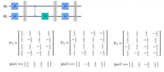
Each dashed line in the circuit drawn is where we took the samples of the quantum statevector and unitary operator of the system.
There are few methods to implement the code above, I think that using the Operator and Statvector classes is the most convenient way.
