3

enter image description here

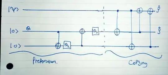
Above is a circuit for "Approximate Quantum Cloning" The preparation state is given by $$|\psi\rangle =\alpha|0\rangle+\beta|1\rangle$$ The gates labelled $\theta_i$ denote single qubit rotations given by $$R_y(-2\theta_i)=\begin{bmatrix}\cos\theta_i&\sin\theta_i\\-\sin\theta_i&\cos\theta_i\end{bmatrix} $$ i.e Counterclockwise rotations of angle $-2\theta_i$ about the y-axis on Bloch Sphere.

Each gate rotation is given by:

$\cos2\theta_1 =\frac{1}{\sqrt5}$

$\cos2\theta_2 =\frac{\sqrt5}{3}$

$\cos2\theta_3 =\frac{2}{\sqrt5}$

Question: Show at the end of the preparation stage the two qubits initially in the state $|00\rangle$ are transformed into the state $$|\phi\rangle =\frac{1}{\sqrt6}(2|00\rangle+|01\rangle+|11\rangle) $$

I'm quite unsure of how to approach this, as it is my first time dealing with a circuit like this. Are the two $|0\rangle$ states said to be entangled, hence the double $|00\rangle$ notation, I thought of applying the rotations to each qubit individually, along with a $\hat C_x $gate operation?
glS
  • 27,510
  • 7
  • 37
  • 125
Dwye
  • 131
  • 1

2 Answers2

3

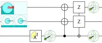
The fastest way to check is with a simulator:

enter image description here

You can tell 00 has twice the amplitude of 11 (and 10) because their probabilities have a $2^2:1$ proportion. You can tell the phases are right because all the blue circles have indicators pointing directly to the right.

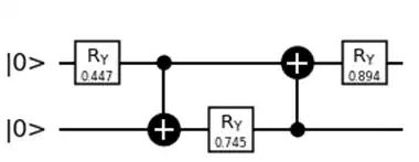
The circuit being used is a bit inefficient. You can get the same state from one CNOT instead of two, and without so many strange angles:

enter image description here

Where the gate $p:q$ has matrix $\sqrt{\frac{1}{p+q}} \begin{bmatrix} \sqrt{p} & -\sqrt{q} \\ \sqrt{q} & \sqrt{p} \end{bmatrix}$.

The simulator is also handy for checking that this is in fact an approximate cloning circuit. Note how the two output bloch sphere displays are pointing in the same direction as the input bloch sphere display, but are a bit shorter.

enter image description here

Craig Gidney
  • 44,299
  • 1
  • 41
  • 116
1

One way to do this is simply working through the quantum circuit one step at a time.

Note that your preparation circuit for the state $|\phi\rangle$ can be written as:

enter image description here

The initial state is $|00\rangle = \begin{pmatrix} 1 \\ 0 \\ 0 \\ 0 \end{pmatrix} $.

The circuit itself has the matrix representation of:

$$ \big( R_Y(\theta_3) \otimes I \big) \cdot CNOT_{10} \cdot \big(I \otimes R_Y(\theta_2) \big) \cdot CNOT_{01} \cdot \big( R_Y(\theta_1) \otimes I\big) $$

Here note that by definition of CNOT gate, we have

$$ CNOT_{01} =|0\rangle \langle 0| \otimes I + |1 \rangle \langle 1| \otimes X = \begin{pmatrix} 1 & 0 & 0 & 0\\ 0 & 1 & 0 & 0\\ 0 & 0 & 0 & 1\\ 0 & 0 & 1 & 0 \end{pmatrix} $$

$CNOT_{10} = I \otimes |0\rangle\langle0| + X \otimes|1\rangle \langle 1|= \begin{pmatrix} 1 & 0 & 0 & 0\\ 0 & 0 & 0 & 1 \\ 0 & 0 & 1 & 0\\ 0 & 1 & 0 & 0 \end{pmatrix}$

and also note that $$R_Y(\theta) \otimes I = \begin{pmatrix} \cos{\theta} & \sin{\theta} \\ -\sin{\theta} & \cos{\theta} \end{pmatrix} \otimes \begin{pmatrix} 1 & 0 \\ 0 & 1 \end{pmatrix} = \begin{pmatrix} \cos{\theta} \cdot \begin{pmatrix} 1 & 0 \\ 0 & 1 \end{pmatrix} & \sin{\theta} \cdot \begin{pmatrix} 1 & 0 \\ 0 & 1 \end{pmatrix} \\ -\sin{\theta} \cdot \begin{pmatrix} 1 & 0 \\ 0 & 1 \end{pmatrix} & \cos{\theta} \cdot \begin{pmatrix} 1 & 0 \\ 0 & 1 \end{pmatrix} \end{pmatrix} $$

Going through this calculation will get your desire state.

KAJ226
  • 14,182
  • 2
  • 12
  • 34