8

I've been experimenting with quantum circuits and can't quite fathom how the difference between states comes together.

Speaking in terms of simulations using qiskit, the following code yelds the same results:

circuit = QuantumCircuit(1)
circuit.h(0)
state = Statevector.from_instruction(circuit)
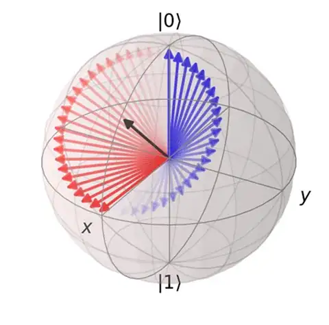
display(plot_bloch_multivector(state, title="H", reverse_bits=False))

circuit = QuantumCircuit(1) circuit.ry(0.5*np.pi,0) state = Statevector.from_instruction(circuit) 
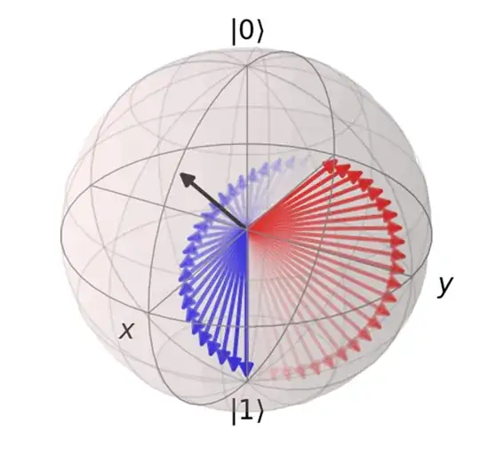
display(plot_bloch_multivector(state, title="Y", reverse_bits=False))

enter image description here

According to this page, the H-Gate is equivalent to the following circuit:

enter image description here

The state vector remains the same, which makes sense as it's only rotating around the x-axis.

Even negating the initial qubit state and make it a $|1\rangle$ does not bring any difference to the table.

So, I went deeper and looked at the maths behind it. Applying the H gate to $|0\rangle$ results in:

$$ H|0\rangle =\ \begin{pmatrix} \frac{1}{\sqrt{2}} & \frac{1}{\sqrt{2}}\\ \frac{1}{\sqrt{2}} & -\frac{1}{\sqrt{2}} \end{pmatrix} \begin{pmatrix} 1 \\ 0 \end{pmatrix} =\ \begin{pmatrix}\frac{1}{\sqrt{2}} \\ \frac{1}{\sqrt{2}}\end{pmatrix} =\ \frac{|0\rangle + |1\rangle}{\sqrt{2}} =\ |+\rangle $$

Now, using the RY-Gate, we can construct a matrix using $\frac{\pi}{2}$. This is where my understanding of the mathematical application stops tho, and I can't quite figure out how to do the rest of the calculation. This is as far as I've come, but I can't quite "translate" the result into a comparable qubit state:

$$ \begin{pmatrix} \cos(\frac{\pi}{4}) & -\sin(\frac{\pi}{4})\\ \sin(\frac{\pi}{4}) & \cos(\frac{\pi}{4}) \end{pmatrix}|0\rangle =\ \begin{pmatrix} 0.707 & -0.707\\ 0.707 & 0.707\end{pmatrix} \begin{pmatrix} 1 \\ 0 \end{pmatrix} =\ \begin{pmatrix} 0.707 \\ 0.707 \end{pmatrix} $$

Reason for this question is that I am trying different circuits to classify IRIS for comparison, and I am seeing much better accuracy when using my basic Y-Rotation based circuit in comparison to qiskits ZZFeature and RealAmplitudes circuit.

Ricardo
  • 199
  • 2
  • 9

3 Answers3

15

While Hadamard gate is defined as $$ H= \frac{1}{\sqrt{2}} \begin{pmatrix} 1 & 1 \\ 1 & -1 \end{pmatrix}, $$ $y$-rotation by $\pi/2$ leads to gate $$ Ry(\pi/2)= \frac{1}{\sqrt{2}} \begin{pmatrix} 1 & -1 \\ 1 & 1 \end{pmatrix}. $$ So, there is a difference in position of -1 in the second column. Application of the $X$ gate returns the -1 in $Ry(\pi/2)$ to right place to obtain Hadamard gate.

You can easily see that $H|0\rangle = \frac{1}{\sqrt{2}}(|0\rangle + |1\rangle)$ and $Ry(\pi/2)|0\rangle = \frac{1}{\sqrt{2}}(|0\rangle + |1\rangle)$. Application of $X$ after $Ry$ leads to the same quantum state.

However, while $H|1\rangle = \frac{1}{\sqrt{2}}(|0\rangle - |1\rangle)$, $Ry(\pi/2)|1\rangle = \frac{1}{\sqrt{2}}(-|0\rangle + |1\rangle)$. Application of $X$ after $Ry$ switches states $|0\rangle$ and $|1\rangle$ and leads to $XRy(\pi/2)|1\rangle = \frac{1}{\sqrt{2}}(|0\rangle - |1\rangle)$.

This all means that $XRy(\pi/2)=H$.

Martin Vesely
  • 15,244
  • 4
  • 32
  • 75
5

The algebraic comparison of the operations is, of course, correct.

Additionaly, noting that $H$ is Hermitian, we see that $R_y\left(\frac{\pi}{2}\right)$ is not Hermitian, and must be transformed.

A more intuitive approach is to examine the effect of the rotations on the Bloch sphere. Note that the H gate is a rotation about an axis which is on the X-Z plane, in the middle between the X and Z axes, as shown:

When we perform a 90° rotation about the Y axis, $R_y\left(\frac{\pi}{2}\right)$:

We seem to have the correct result, namely $|0\rangle\rightarrow|+\rangle,|1\rangle\rightarrow|-\rangle$.

However, on closer inspection, we see that the original x axis is now pointing "down", whereas the H gate results in the x axis pointing up ($|+\rangle$ changing places with $|0\rangle$).

Moreover, if we apply $R_y\left(\frac{\pi}{2}\right)$ again, we get the wrong result: $|+\rangle \rightarrow |1\rangle$ instead of $|0\rangle$, and $|-\rangle \rightarrow |0\rangle$ instead of $|1\rangle$

Adding a $\pi$ rotation about the X axis, $R_x\left(\pi\right)=X$, "fixes" the resulting location of the X axis (pointing "up"), making the resulting operation correct (no effect on the $|+\rangle,|-\rangle$ states which are on the X axis, and flipping the $|0\rangle, |1\rangle$ states)

inq
  • 211
  • 2
  • 4
3

Just to emphasise the point on the accepted answer...

The two gates, when applied to a specific state, give the same output. That does not mean they are the same, because the action on another state may be different (and I don't just mean a global phase).

For example, if you take the state $|+\rangle=(|0\rangle+|1\rangle)/\sqrt{2}$ then $$ H|+\rangle=|0\rangle, $$ but $$ R_Y(\pi/2)|+\rangle=|1\rangle. $$ The two outcomes are orthogonal. So, in this case, you can definitely tell which of the two you have just by measuring the output.

DaftWullie
  • 62,671
  • 4
  • 55
  • 140