4

Consider the RL circuit in (a). Figures (b) and (c) represent what happens when one of the two switches is open while the other one is closed (this is discussed in this link). physics_libre_text
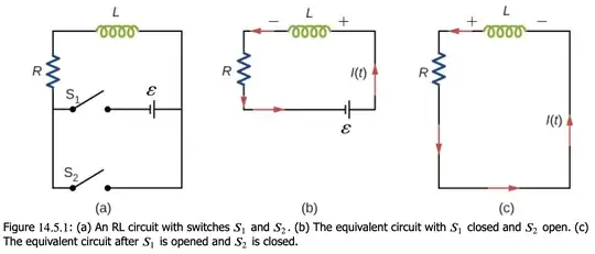
In figure (b), where $S_1$ is closed, the circuit basically consists of a resistor, an inductor and a cell. In figure (c), where $S_1$ is opened and $S_2$ is closed, it reduces to a resistor and an inductor only.

When both $S_1$ and $S_2$ are open, no current flows in the circuit. Suppose that in $t=0$ the switch $S_1$ is closed. Applying Kirchhoff's second law, it can be seen that the current $i(t)$ is described by the following function, which is the solution of a non-homogeneous first-order ODE: $$i(t)=\frac{\epsilon}R\left(1-e^{-\frac RL t}\right)=\frac{\epsilon}R\left(1-e^{-\frac t \tau}\right).$$

After enough time, the current is very close to $\frac{\epsilon}R $. Then, letting $t=0$ be the time when $S_1$ gets opened and $S_2$ closed, with $i(0)=\frac{\epsilon}R$, one finds that $$i(t)=\frac{\epsilon}Re^{-\frac t \tau}.$$

This is precisely what we would expect: if the cell is "bypassed", then the current will eventually vanish, while the energy will be dissipated in the resistor and stored in the inductor.

What would happen, however, if instead of "bypassing" the cell with the bottom part of the circuit, I only opened $S_1$ after the current gets close to $\frac{\epsilon}R$? I could not apply Kirchhoff's loop rule (as my open circuit would not be a loop anymore). When approaching the switches, the current would be "stuck". I guess that it would not stop flowing immediately, but I don't get where it could go. How can I determine an equation describing the current in this case?
2 Answers2

8

Since you can’t change the current in an ideal inductor in zero time, in real life an attempt to stop the current by opening S1 will cause the inductor to generate a large voltage across the switch air gap causing the air to break down (ionize).

This will result in briefly maintaining current across the gap, until the energy stored in the inductor’s magnetic field prior to opening switch is dissipated as heat in the arc and resistor.

This is why switching inductive loads can be brutal on air gap switches. Such switches need to be rated for inductive loads with additional means sometimes used to reduce arcing, such as the placement of a suitably rated capacitor across the contacts.

Hope this helps.

Bob D
  • 81,786
4

I could not apply Kirchhoff's loop rule (as my open circuit would not be a loop anymore). You can because the open switch can act as a capacitor.

In terms of energy the inductor has $\frac 12Li^2$ which it needs to get rid of when the switch is opened.
One way is exceeding the breakdown potential of the air between the switch contacts so that the air becomes a conductor due the large emf induced in the circuit because of the rapid change of current (and hence flux linked with the circuit: Faraday's law) and the energy which was stored in the inductor is dissipated within the air between the switch contacts and the resistor in the circuit.

If the air does not break down then the switch acts as a capacitor and now you have an $LCR$ circuit with a natural frequency of oscillation $\omega^2 = \frac{1}{ LC}$.
So the current in the circuit will exhibit damped shm and the energy is dissipated in the resistor.

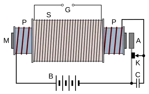
One form of transformer is the basis of an (induction) coil which is used to produce high voltages using an interrupted low voltage dc supply - Please help identify this physics apparatus! - and to prevent the arcing across a switch a capacitor $C$ was placed across the switch $K$.

enter image description here.

Before the advent of modern electronics such a coil was used to provide the voltage which produced the spark in a petrol internal combustion engine and the switch was called the contact breaker points which had a capacitor across them.

To demonstrate the rise and then decay of current in an $LR$ circuit one could use a make before break switch instead of $S_1$ and $S_2$. - Significance of sliding switch in a LR circuit.

Farcher
  • 104,498