1

I have been trying to understand torque around the instantaneous axis of rotation of rigid bodies rolling without slipping down an incline. This instantaneous axis is at the point of contact between the rolling object and the incline.

Several other threads in this stackexchange have discussed how the related scenario of an object sliding without friction doesn't rotate because of the cancellation of torques from gravity and pseudotorque from the non-inertial frame, both acting around the instantaneous axis of rotation.

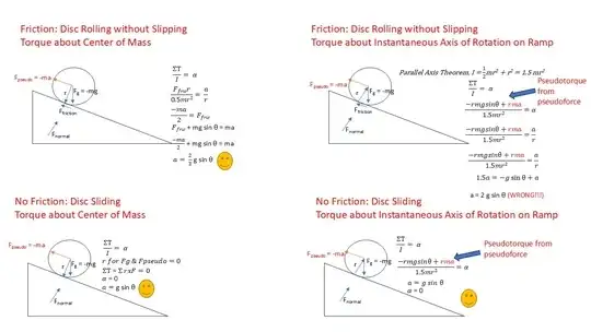
However, when I try to calculate the acceleration of a rolling disc down an incline using a similar approach, I fail to get the correct expression of acceleration = (2/3) g sin theta. Instead I am calculating 2 g sin theta.

I put together a set of force diagrams for four scenarios in a 2x2 matrix (no friction vs friction, torque around c.o.m. vs torque around instantaneous axis of rotation).

I'd really appreciate any feedback about the error in my approach or misunderstanding of how/when to use pseudoforces and pseudotorques. I've read through a number of other threads in this forum and there was one extended discussion where this issue was raised but without the counterexample diagrams that I am including. Ball Rolling Down An Inclined Plane - Where does the torque come from?

(I thought that I understood the convenience of choosing an axis that coincides with the center of mass so that the non-inertial pseudoforces don't influence torque since they effectively act at the c.o.m. with a radius of 0. I also thought that I understood that the angular acceleration in the c.o.m. frame will be the same in the laboratory frame, and that the tangential acceleration in the c.o.m. frame represents the linear translational acceleration in the laboratory frame.)
enter image description here

lamplamp
  • 1,668

3 Answers3

0

Instead I am calculating 2 g sin theta.
With no slipping there is no pseudo-force as you are in an inertial frame.

That is why the instantaneously at rest contact point between the rolling object and the slope is used in such problems.

Also the accelerating centre of mass is used as the the line of action of the pseudo-force passes through the centre of mass.

Farcher
  • 104,498
0

I think you must consider the kinematics of the problem first before trying to work out the dynamics. Here is where you sum of torques about the center of mass and not the IAR.

I always find the following process to always give out correct answers and to methodically consider the situation at hand. As the level of complexity arises this process will not fail you.

Kinematics

Consider the speed $v$ describing tangential velocity down the ramp, and corresponding acceleration $a$. Also consider the rotation $\omega$ as acting clockwise, producing the material speed of whatever particle is in contact with the ground, being fixed, as

$$ v - \omega \, r = 0 \tag{1} $$

This imposes the kinematic constraint in acceleration form as a direct derivative

$$ a - \alpha \, r = 0 \tag{2} $$

Note the above is not the material acceleration of the particle in contact, which includes other terms.

Dynamics

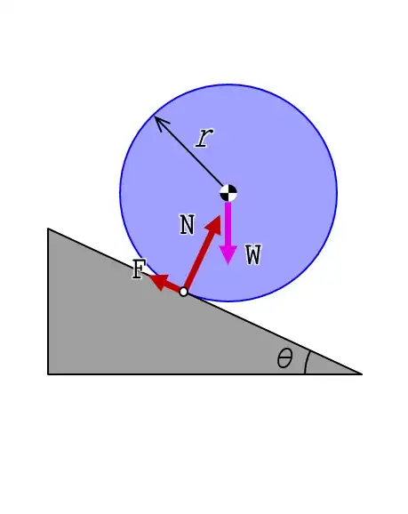
Looking at the forces acting on the body, you have $W = m g$ the weight acting downwards from the COM, $N$ the normal force acting away from the surface at the contact point, and $F$ any friction needed at the contact point to impose the constraint (2)

fig1

The net forces and torques about the center of mass are shown below, in coordinates aligned with the ramp (for simplicity)

$$\begin{aligned} -F + (m g \sin \theta) & = m\, a \\ N - (m g \cos \theta) & = 0 \\ r F & = I_{\rm C} \alpha \\ \end{aligned} \tag{3}$$

The mass moment of inertia of disk about its center of mass is $ I_{\rm C} = \tfrac{1}{2} m r^2$

Solution

Together with (2), the above has a solution of

$$\begin{cases} a & = \frac{m g r^2 \sin \theta}{I_{\rm C} + m r^2} \\ \alpha & = \frac{m g r \sin \theta}{I_{\rm C}+ m r^2} \\ \hline F & = \frac{I_{\rm C} m g \sin \theta}{I_{\rm C}+ m r^2} \\ N & = m g \cos \theta \\ \end{cases} \tag{4}$$

When the MMOI is used in $a$ above the result is the correct answer.

$$\boxed{a = \tfrac{2}{3} g \sin \theta} \tag{5}$$

jalex
  • 3,765
0

From the FBD you obtain:

$$m\,a=m\,g\,\sin(\theta)+F\tag 1$$ $$I_c\,\alpha=-F\,r\tag 2$$

and the rolling condition

$$ a-r\,\alpha=0\tag 3$$

multiply equation (1) with r and add to equation (2) :

$$m\,a\,r+\frac m2 r^2\,\alpha=m\,g\,\sin(\theta)\,r\tag 4$$

substitute form equation (3) $~\alpha=a/r~$ :

$$m\,a\,r+\frac m2 r^2\,\frac ar=m\,g\,\sin(\theta)\,r\quad\Rightarrow a=\frac 23\,g\sin(\theta)$$

you can obtain this result by taking the sum of the torques at the contact point A

$$m\,a\,r+I_c\alpha=m\,g\,\sin(\theta)\,r\\ m\,a\,r+\frac m2\,r^2\,\frac ar=m\,g\,\sin(\theta)\,r\quad\Rightarrow a=\frac 23\,g\sin(\theta)$$

or, with $$ I_A\,\alpha=m\,g\,\sin(\theta)\,r\\I_A=\frac m2\,r^2+\,m\,r^2=\frac 32\,m^2\,r^2\quad ,\alpha=a/r\quad\Rightarrow\\a=\frac 23\,g\sin(\theta)$$

With friction force $~F_\mu~$

$$m\,a=m\,g\,\sin(\theta)-F_\mu$$ $$I_c\,\alpha=+F_\mu\,r$$

Eli
  • 13,829