The Instant Centre of Rotation (IAR) is not a physical point and doesn't obey any laws as far as placement or continuity. It can be in one location at one instant, and another location in the next instant.
There is also no law that constrains the IAR to be on a physical body. Take the simplest example of a record spinning on a record player. The record is rotating about its center, but there is a hole in the center.
The IAR is a mathematical construct in order to describe the velocity field of a rigid body without having to specify the velocity of every point on the body.
Just the position of the IAR point and the rate of rotation is sufficient information to fully describe the motion of a 2D body at any instant.
Now for 3D you have an axis in space (described by a point and a direction) and you can describe the motion of any point in space as a rotation about the axis plus a parallel translation along the axis.
The kinematics of 2D rigid body are such that the motion of the body can always decomposed by the "velocity of a point" on the body (or not on the body, but co-moving with the body, what is called the extended frame) and a rotation about that point.
Finding the IAR is finding the unique special point that remains motionless and all the other points revolve around it.
This sets up a velocity field around the IAR which that the distance to the IAR defines the velocity of any point in space in terms of its magnitude, and the direction is perpendicular to the relative position of the point.
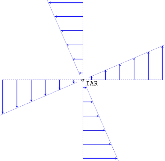
If you place an origin at the IAR and look at any point in space $(x,y)$, then the velocity vector in space is fully defined as
$$ \vec{v} = \pmatrix{ -y\, \omega \\ x \, \omega} $$
Note the above is 2D projection of the 3D vector equation $$\vec{v} = \vec{\omega} \times \vec{r}$$
Here is an important concept that directly answers your question.
Define an extended frame as a collection of massless particles that are fixed with each other (like a rigid body) that extends out to infinity and is co-moving with the physical body. This is called the extended frame.
Now the relationship $$\vec{v} = \pmatrix{ -y\,\omega \\ x\,\omega}$$ applies to the entire 2D space and describes that velocity of all points on the body and beyond on the extended frame.
In more general terms if $(x_{\rm IAR},y_{\rm IAR})$ is the location in space of the IAR, and $(x,y)$ is the location of some other point in space, then
$$ \vec{v}(x,y) = \pmatrix{-(y-y_{\rm IAR}) \omega \\ (x-x_{\rm IAR}) \omega} \tag{1} $$
describes the velocity of that point (being a physical point or not). Think of it like placing a magnifying glass at $(x,y)$ and measuring the velocity of whatever particle happens to pass under it at any instant. And if no physical particle is under the magnifying glass, you think of the massless particles of the extended frame and their velocity.
How to reverse the process and find the IAR location from known velocities.
Just knowing the velocity of a single point isn't sufficient because the body could be translating with this velocity, or it could be rotating about the IAR
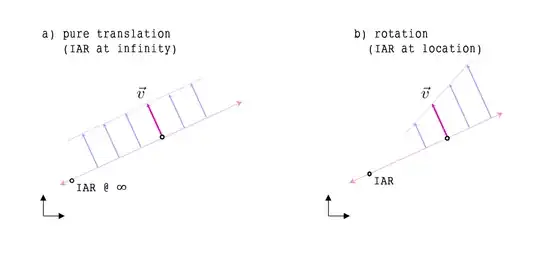
Either way, you can say that the IAR lies somewhere on the line (purple line above) that goes through the particle of which velocity we know, and extends perpendicularly out to infinity.
a. For the case of rotation, the IAR exists at a finite point somewhere along this line.
b. For the case of translation, the IAR exists at a point on the horizon that exists an infinite distance away. (Imagine you are standing on the plane where these objects exist, and imagine how parallel lines meet at infinity at the horizon like rail tracks).
In summary, given one point and its velocity we construct the purple line above and state that the IAR exists somewhere along this line.
To get the location of the IAR we need two reference points, and their velocities, and where the two perpendicular lines meet is the only location the IAR can exist. This is because it has to be along both lines, and it is unique.
A practical example of all the concepts above. Find the IAR for the middle bar (BC) in a four-bar linkage ABCD.
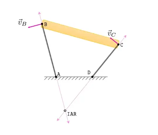
The support bars AB and CD pivot about the ground at points A and D respectively by some unknown magnitude rotation.
The resulting velocity at B $\vec{v}_B$ must be perpendicular to AB since it belongs to the extended frame of the body AB that rotates about A.
The resulting velocity at C $\vec{v}_C$ must be perpendicular to CD since it belongs to the extended frame of the body CD that rotates about D.
The middle body BC must match velocities at B and C which means its extended frame has an IAR that is somewhere along the AB line and the CD line at the same time.
Where the two purple lines meet, is the IAR for body BC. You can verify this by drawing lines that start from the IAR the velocity should be perpendicular to every point along those lines (first graph in this post) and thus the velocity at B is indeed perpendicular to AB and the velocity at C in indeed perpendicular to CD. Both of these conditions are met by the placement of IAR where I have it drawn.
The special case of translating points is the last part to consider. In the ladder shown in the question is almost identical to the figure above. But instead of the finite length support arms AB and CD, consider some infinite long support bars that are pivoted at infinity. They can still result in $\vec{v}_B$ and $\vec{v}_C$ in the directions shown above, the IAR is still in the location of the intersection just as before.
The only difference is that at different time frames the four-bar linkage has different directions of the end point velocities, and for the sliding ladder the directions of the end point velocities remains fixed at all times, as the points translate along the walls, instead of tracking arcs.
The above will help you find the IAR using the geometric method by drawing lines and finding where they meet. There is a law that states the IAR of two connected bodies forms a line, and the relative rotation of the two bodies defined by the connection must also lie on this line. In the example above, the IAR of body AB is at A. The relative rotation between AB and BC a pivot about B, hence the IAR of BC is along the line connecting A and B.
Finding the IAR mathematically is pretty simple actually. I am going to present the 3D equation, knowing that in 2D you just project the vectors down to a plane.
Given a rigid body that rotates with known rotational velocity $\vec{\omega}$ and also we know some reference point A on the extended frame has velocity $\vec{v}_A$, then the location if of the IAR is given by
$$ \vec{r}_{\rm IAR} = \vec{r}_A + \frac{ \vec{\omega} \times \vec{v}_A } { \| \vec{\omega}\|^2} \tag{2}$$
In 2D the above is
$$ \pmatrix{ x_{\rm IAR} \\ y_{\rm IAR} } = \pmatrix{x_A \\ y_A} + \pmatrix{ - \frac{ vy_A}{\omega} \\ \frac{vx_A}{\omega} } \tag{3}$$


