$\def \b {\mathbf}$
To obtain the transformation matrix between the Body system and Inertial system $~\b R(t)~$ you can use those two methods
Method I
with the transformation matrix
\begin{align*}
&\b R=\b R_z(\psi)\,\b R_y(\theta)\,\b R_x(\phi)
\end{align*}
where $~\psi~$ is the yaw angle, $~\theta~$ is pitch angle and $~\phi~$ is the roll angle.
from the transformation matrix you obtain
\begin{align*}
&\begin{bmatrix}
\dot{\phi} \\
\dot{\theta} \\
\dot{\psi} \\
\end{bmatrix}=
\left[ \begin {array}{ccc} 1&{\frac {\sin \left( \theta \right) \sin
\left( \phi \right) }{\cos \left( \theta \right) }}&{\frac {\sin
\left( \theta \right) \cos \left( \phi \right) }{\cos \left( \theta
\right) }}\\ 0&\cos \left( \phi \right) &-\sin
\left( \phi \right) \\ 0&{\frac {\sin \left( \phi
\right) }{\cos \left( \theta \right) }}&{\frac {\cos \left( \phi
\right) }{\cos \left( \theta \right) }}\end {array} \right]
\,\begin{bmatrix}
\omega_1(t) \\
\omega_2(t) \\
\omega_3(t) \\
\end{bmatrix}\tag 1
\end{align*}
for a given $~\omega_i(t)~$ the solution of those 3 differential equations with the initial conditions
$~\psi(0)=0~,\theta(0)=0~,\phi(0)=0~$ is
$~\psi(t)~,\theta(t)~,\phi(t)~$
Method II
\begin{align*}
&\b{\dot{R}}=\b R\, \left[ \begin {array}{ccc} 0&-\omega_{{3}} \left( t \right) &\omega_{
{2}} \left( t \right) \\ \omega_{{3}} \left( t
\right) &0&-\omega_{{1}} \left( t \right) \\ -
\omega_{{2}} \left( t \right) &\omega_{{1}} \left( t \right) &0
\end {array} \right]
\tag 2
\end{align*}
the solution of the 9 differential equations with the initial conditions
$~R_{11}(0)=1 ,~R_{22}(0)=1 ,~R_{33}(0)=1\quad, R_{ij}(0)=0~, i\ne j$
is the transformation matrix $~\b R(t)~$, where the input is the angular velocities $~\omega_i(t)~$
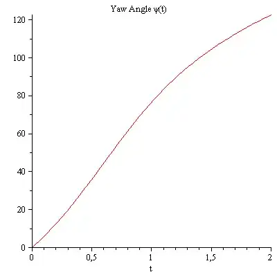
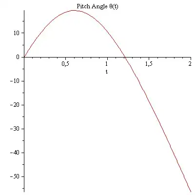
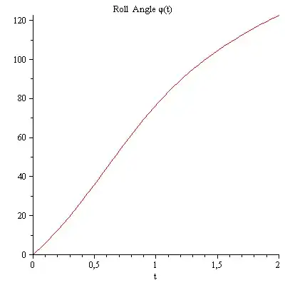
yaw ,pitch ,roll angles
\begin{align*}
&\psi(t)=\arctan\left(R(t)_{21},R(t)_{11}\right)\\
&\theta(t)=\arctan\left(-R(t)_{31},\sqrt{R(t)^2_{11}+R(t)^2_{21}}\right)\\
&\phi(t)=\arctan(R(t)_{32},R(t)_{33})
\end{align*}
Simulation
\begin{align*}
\b\omega(t)=\begin{bmatrix}
1 \\
1 \\
1 \\
\end{bmatrix}
\end{align*}
compare the yaw, pitch and roll angles both methods
Remarks
the body fixed coordinate system is located at the center of mass where the x- axis is to the front, the y-axis to the left and the z-axis $~\b z=\b x\times \b y~$
the components of angular velocity vector $~\b\omega~$ are given in body system
with equation (1), you get singularity if the pitch angle $~\theta=\pi/2~$
it is easy to use equation (1) then equation (2)
How to obtain for a arbitrary rotation matrix the yaw pitch and roll angles
compare arbitrary rotation matrix R with the rotation matrix of method I.
\begin{align*}
& \left[ \begin {array}{ccc} R_{{1,1}}&R_{{1,2}}&R_{{1,3}}
\\ R_{{2,1}}&R_{{2,2}}&R_{{2,3}}
\\ R_{{3,1}}&R_{{3,2}}&R_{{3,3}}\end {array}
\right] =\b R_z(\psi)\,\b R_y(\theta)\,\b R_x(\phi)=\\&\left[ \begin {array}{ccc} \cos \left( \psi \right) \cos \left(
\theta \right) &-\sin \left( \psi \right) \cos \left( \phi \right) +
\cos \left( \psi \right) \sin \left( \theta \right) \sin \left( \phi
\right) &\sin \left( \psi \right) \sin \left( \phi \right) +\cos
\left( \psi \right) \sin \left( \theta \right) \cos \left( \phi
\right) \\ \sin \left( \psi \right) \cos \left(
\theta \right) &\cos \left( \psi \right) \cos \left( \phi \right) +
\sin \left( \psi \right) \sin \left( \theta \right) \sin \left( \phi
\right) &-\cos \left( \psi \right) \sin \left( \phi \right) +\sin
\left( \psi \right) \sin \left( \theta \right) \cos \left( \phi
\right) \\ -\sin \left( \theta \right) &\cos
\left( \theta \right) \sin \left( \phi \right) &\cos \left( \theta
\right) \cos \left( \phi \right) \end {array} \right]\\
&\Rightarrow\\
&\tan(\psi)=\frac{R_{21}}{R_{11}}\quad,
\tan(\theta)=\frac{-R_{31}}{\sqrt{R^2_{11}+R^2_{21}}}\quad,
\tan(\phi)=\frac{R_{32}}{R_{33}}
\end{align*}
to avoid singularity one can use instead of the Euler angles
quaternion $~\b q\,(4\times 1)~$
The relationship between quaternions and angular Velocity vector
\begin{align*}
\underbrace{\begin{bmatrix}
\dot{q}_w \\
\dot{q}_x \\
\dot{q}_y \\
\dot{q}_z \\
\end{bmatrix}}_{\b{\dot{q}}}=\frac{1}{2}
\left[ \begin {array}{cccc} 0&-\omega_{{x}}&-\omega_{{y}}&-\omega_{{z
}}\\ \omega_{{x}}&0&\omega_{{z}}&-\omega_{{y}}
\\ \omega_{{y}}&-\omega_{{z}}&0&\omega_{{x}}
\\ \omega_{{z}}&\omega_{{y}}&-\omega_{{x}}&0
\end {array} \right]\,\underbrace{\begin{bmatrix}
{q}_w \\
{q}_x \\
{q}_y \\
{q}_z \\
\end{bmatrix}}_{\b q(t)}
\end{align*}
where the components of $~\b\omega~$ is given in body system
solving the differential equations with the initial conditions
$q_1(0)=1~,q_i(0)=0~,i=2..4~$ you obtain the solution $~\b q(t) ~$ where $~\b q(t)\,\cdot\,\b q(t)=1~$
The rotation matrix between the body and inertial system ,corresponding to a quaternion $\b {q}$
\begin{align*}
\b R=\left[ \begin {array}{ccc} {q_{{1}}}^{2}+{q_{{2}}}^{2}-{q_{{3}}}^{2}-
{q_{{4}}}^{2}&-2\,q_{{1}}q_{{4}}+2\,q_{{2}}q_{{3}}&2\,q_{{1}}q_{{3}}+2
\,q_{{2}}q_{{4}}\\ 2\,q_{{1}}q_{{4}}+2\,q_{{2}}q_{{3
}}&{q_{{1}}}^{2}+{q_{{3}}}^{2}-{q_{{4}}}^{2}-{q_{{2}}}^{2}&-2\,q_{{1}}
q_{{2}}+2\,q_{{3}}q_{{4}}\\ -2\,q_{{1}}q_{{3}}+2\,q_
{{2}}q_{{4}}&2\,q_{{1}}q_{{2}}+2\,q_{{3}}q_{{4}}&{q_{{1}}}^{2}+{q_{{4}
}}^{2}-{q_{{2}}}^{2}-{q_{{3}}}^{2}\end {array} \right]
\end{align*}


