My question is a follow-up to this one.
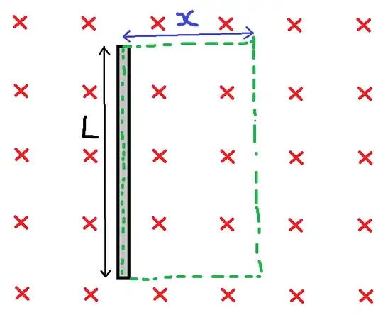
The green dotted line is the arbitrary loop which is constructed in the calculation of emf in the wire of length L. x is a variable which can be changed to alter the size of the loop. The red crosses are the flux density vectors of a uniform magnetic field.
In the linked question (Scenario 1), my understanding of the answer is:
- Induced emf around a loop is equal to the rate of change of flux through the loop $\sum_{}^{}(t)$ with respect to time.
- The flux through the loop is the surface integral $\phi_B = \iint_{\sum_{(t)}^{}}^{}\textbf{B}(t).d\textbf{A}$ . The induced emf $\varepsilon=-\frac{d \phi_B}{dt}$ (wikipedia faradays law of induction).
- The loop path is arbitrary as long as it contains the straight wire i.e. the parameter x is arbitrary.
- Because the loop is drawn in the diagram frame of reference and the wire is in motion, this means that the area of the loop is changing and therefore the flux through the loop is changing and an emf is induced.
- No matter how large the parameter x is the rate of change of the loop area will be the same. Good.
Altering this scenario slightly - (Scenario 2) if the wire is held stationary in the diagram frame of reference and the source of the uniform magnetic field is now in motion moving to the left at constant velocity V. Following my logic from the steps above and drawing the loop still in the diagram/wire frame of reference:
- The area of the loop of arbitrary size is not changing with respect to time.
- The flux through the loop is not changing because the sum of all of the area elements dot product with the flux density is not changing with respect to time.
- No emf is induced around the loop/in the wire.
My question is how does the surface integral form of faradays law arrive at an induced emf in this scenario? Is there some other relativistic affect which I have overlooked?
...
Sorry, I am going to sneak another closely related question on the end here. Imagine the wire and the source of the magnetic field are both stationary in the diagram frame of reference. Only the magnetic field is now changing in such a way that the flux density at every point in space is increasing linearly wrt time. (Scenario 3).
It makes sense to me that an emf is now induced in the wire since the flux through a loop which contains the wire is increasing with time.
My confusion lies in the way the loop is drawn. If we compare x=2 and x=4, then for x=4, at a given point in time there will be more flux through the loop and therefore the rate that flux changes wrt time will be larger and therefore there is a larger emf in the loop.
If using two different values of x will yield a different calculation of emf in the loop/wire then the selection of x cannot be arbitrary? Can anyone point out the point in my thought process where I am going wrong?
Thankyou in advance for any input.
