2

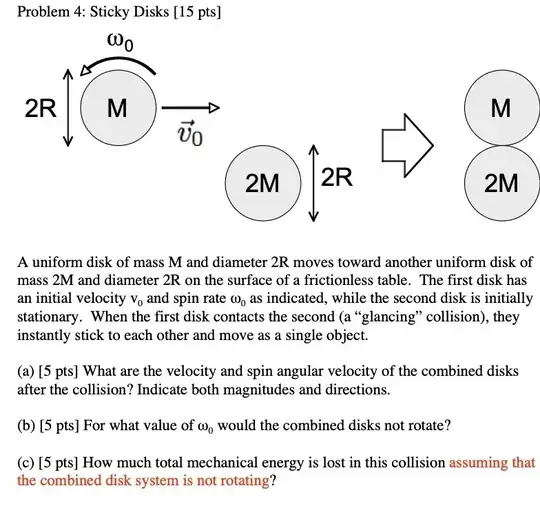
enter image description here

I am working on answering part (a) and here is what I got: By conserving linear momentum, we have that $$mv_0 =(3M)v_f \hspace{3mm}\implies \hspace{3mm} v_f =\frac{1}{3}v_0$$ Now, in order to conserve angular momentum, we have to choose a point from which to calculate the moment of inertia of the system; we choose the center of mass. Choosing the origin to be the center of mass of the $2M$ disk, we have that $$y_{com} =\frac{2RM}{3M} =\frac{2}{3}R$$ That is we have that the center of mass of the system is $\frac{2}{3}$ of the radius away from the center of mass of the $2M$ disk and $\frac{4}{3}$ of the radius away from the center of mass of the $M$ disk. Now, by the parallel axis theorem, the new moment of inertia about the center of mass of the system for the smaller disk is $$I_s =I_{\text{com}}+M\left(\frac{4}{3}R\right)^2 = \frac{1}{2}MR^2 +\frac{16}{9}MR^2 =\frac{41}{18}MR^2$$ and the new moment of inertia for the larger disk is $$I_b =I_{\text{com}}+(2M)\left(\frac{2}{3}R\right)^2 =\frac{1}{2}(2M)R^2+\frac{8}{9}MR^2 =\frac{17}{9}MR^2$$ Hence, our moment will be $$I=I_s+I_b = \frac{25}{6}MR^2$$ Now, for the initial angular momentum about the systems center of mass, we have $$\mathbf{L}_0 = I_s \omega_0^\odot +\left(\frac{4}{3}R\right)Mv_0^\otimes = \left( \frac{41}{18}MR^2 \right)\omega_0^\odot +\left(\frac{4}{3}R\right)Mv_0^\otimes$$ At this point I checked my work with the given solution and I noticed that they used the moment of inertia about the center of mass for the small disk for one part of the calculation and they then used the moment about the center of mass of the system in the same calculation.

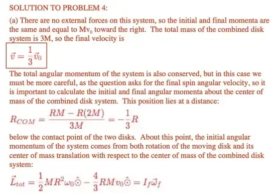
enter image description here

At the bottom line they have given above, it says $$L_0 = \frac{1}{2}MR^2\omega_0 \odot-\text{yada yada}$$ but that's the wrong moment of inertia no? I thought we would have to stay consistent with our choice of axes throughout the entire momentum calculation. Im sure I am missing something small but any guidance would be appreciated.

EDIT: My question is precisely about the underlying physics concepts. I do not want anyone to check my homework and I asked the question after checking to see it it was suitable for the site. It is. My question is:

Why can we choose two different moments of inertia under the same momentum calculation?
3 Answers3

1

At the bottom line they have given above, it says $L_0 = > frac{1}{2}MR^2\omega_0 \odot-\text{yada yada}$ but that's the wrong moment of inertia no? I thought we would have to stay consistent with our choice of axes throughout the entire momentum calculation.

The spin angular momentum of the lightweight disk is the angular momentum of the disk about its own axis of rotation that is comoving with its own centre of mass. This spin angular momentum is independent of where the disk is relative to anything else and independent of its velocity relative to the initial reference frame. It appears you have neglected this term in your calculations. This quantity is part of the total initial angular momentum and is the first term in $L_{tot_{0}} = (1/2)MR^2\omega_0 \ -(4/3)MRv_0 $.

The second term is the angular momentum of the small disk due to its linear motion relative to a chosen axis of rotation. They have chosen the centre of mass of the system, because the angular momentum about this axis gives the spin momentum of the system, which is the solution they are looking for. This point is (4/3)R from the line of motion of the small disk, so the angular momentum due to the linear motion of the small disk is $mvd = Mv_0(4/3)R$ and this quantity is subtracted from the total, because this rotation is in the opposite direction to that of the small disk's spin direction. The large disk is ignored because it has no initial angular momentum.

The important concept here is that for system of particles, the total angular momentum is the sum of all their individual spin momenta (independent of their locations relative to any axis) plus the sum of their individual orbital angular momenta due to their tangential velocities relative to a chosen axis (and distance from the chosen axis is important for this form of angular momentum). You cannot simply calculate the sum of orbital momenta due to motion relative to a chosen axis and ignore the contribution of the spin momenta.

Your calculation using the parallel axis theorem to obtain the total moment of inertia of the system ($I_f$) is not wasted. It is required to calculate the final spin angular velocity ($\omega_{f}$) from $ L_{tot_{0}} = I_{f} \omega_{f} $ Your calculation for $I_{f} $ is correct (I checked).

Now, for the initial angular momentum about the systems center of mass, we have $\mathbf{L}_0 = I_s \omega_0^\odot +\left(\frac{4}{3}R\right)Mv_0^\otimes = \left( \frac{41}{18}MR^2 \right)\omega_0^\odot +\left(\frac{4}{3}R\right)Mv_0^\otimes$

Here you effectively have $I_s \omega_0^\odot = \left( \frac{41}{18}MR^2 \right)\omega_0^\odot$ which implies $I_s = \left( \frac{41}{18}MR^2 \right)$ which is wrong. The moment of inertia of the small disk about its own spin axis is simply $I_s = (1/2)MR^2$ which is what is used to calculate spin angular momentum. Here is an example to demonstrate: Imagine a scenario similar to the one in the OP but neither disk has linear motion. Lets say the small disk has the same angular velocity as in the OP and the large disk has spin angular velocity $\omega_b = 3 \omega_s$, so:

$L_s = I_s \omega_s = (1/2) M R^2 \omega_s = (1/2)MR^2 \omega_s$
$L_b = I_b \omega_b = (1/2) (2M) R^2 (3 \omega_s )= 3MR^2 \omega_s $

The total angular momentum is simply $L_{tot} = L_s + L_b = 3.5 MR^2 \omega_s$. It is as simple as that. Spin angular momentum is always with respect to its own centre of mass and does not care about how far it from any axis of rotation you have chosen for the system. If there were 6 spinning disks we would simply add up all there individual spin momenta, with no adjustment at all for the presumed total moment of inertia of the system. Each disk has it own spin axis. Only orbital angular momentum requires you to allow for tangential velocity of the object relative to some chosen axis and the distance from that chosen axis. It is important to understand the difference between spin and orbital angular momentum.

KDP
  • 10,288
1

First the short answer, then some details about transport of angular momentum.

Short answer

You made a mistake in transporting the momentum from the center of mass of the upper disk to the center of mass, before the collision occurs. This mistake results in the wrong sign of the contribution $\frac{4}{3} M R v_0$.

Some details

Definition of the angular momentum. Being $B$ a system of volume $V$, it's angular momentum w.r.t. a pole $H$ is defined as

$$\boldsymbol{\Gamma}_H = \int_V \rho \left( \mathbf{r} - \mathbf{r}_{H} \right) \times \mathbf{v} \ ,$$

where the integration is performed over the coordinates $\mathbf{r}$ of the points of the body, and $\mathbf{v}$ is the velocity (field) of these points.

Transport of momentum. Next, the angular momentum defined w.r.t. another pole $K$ reads

$$\begin{aligned} \boldsymbol{\Gamma}_K & = \int_V \rho \left( \mathbf{r} - \mathbf{r}_{K} \right) \times \mathbf{v} = \\ & = \int_V \rho \left( \mathbf{r} - \mathbf{r}_{H} + \mathbf{r}_H - \mathbf{r}_K \right) \times \mathbf{v} = \\ & = \int_V \rho \left( \mathbf{r} - \mathbf{r}_{H} \right) \times \mathbf{v} + \int_V \rho \left( \mathbf{r}_H - \mathbf{r}_K \right) \times \mathbf{v} = \\ & = \boldsymbol{\Gamma}_H + \left( \mathbf{r}_H - \mathbf{r}_K \right) \times \mathbf{Q} \ , \end{aligned}$$

being $\mathbf{Q} = \int_V \rho \mathbf{v} = m \mathbf{v}_G$ the momentum of the body $R$ with center of mass $G$.

Conservation of momentum and angular momentum in collisions. In a collision, it's usually assumed that external forces has minor influence if compared with internal impulsive forces (as a good approximation of large forces for small time intervals), and thus the conservation of momentum and angular momentum across the collision is assumed to hold

$$\Delta \mathbf{Q} = \mathbf{0} \qquad , \qquad \Delta \boldsymbol{\Gamma}_H = \mathbf{0} \ .$$

in the small time interval when the collision occurs.

Solution of the exercise. The mistake you make is in the transport of the momentum of the system before the collision occurs. Choosing a pole $K$ with the same $y$-coordinate as the center of mass of the two disks, it is $\frac{4}{3} R$ under the center of the upper disk. The moment of inertia (or better, the $z,z$-component! The rotational inertia is represented by a symmetric $2^{nd}$-order tensor in general) of the upper disk is $I = \frac{1}{2}M R^2$ the angular velocity can be represented as $\boldsymbol{\omega} = \omega_0 \mathbf{\hat{z}}$, with the unit vector $\mathbf{\hat{z}}$ pointing outwards the screen of the device, and using the RHS hand rule for signs.

Now, let's evaluate the transport of momentum and evaluate $\boldsymbol{\Gamma}_K$ with the formula given above

$$\begin{aligned} \boldsymbol{\Gamma}_K & = \boldsymbol{\Gamma}_H + \left( \mathbf{r}_H - \mathbf{r}_K \right) \times \mathbf{Q} = \\ & = \frac{1}{2} M R^2 \omega_0 \mathbf{\hat{z}} + \frac{4}{3} R \times M v_0 \mathbf{\hat{x}} = \\ & =\frac{1}{2} M R^2 \omega_0 \mathbf{\hat{z}} - \frac{4}{3} M R v_0 \mathbf{\hat{z}} = \\ & = \left[ \frac{1}{2} M R^2 \omega_0 - \frac{4}{3} M R v_0 \right] \mathbf{\hat{z}} \end{aligned}$$

basics
  • 13,368
1

Here is a graphical answer which I think is very intuitive and simpler to follow than a purely algebraic one IMHO.

fig1

If you know that after the collision the combined center of mass is translating, and there is no rotation, then angular momentum resolved about the combined center of mass should be zero, both before and after the impact (due to conservation).

In fact, the dashed blue line above shows the axis of percussion which is the locus of points whose total angular momentum is zero. This is kind of the definition of the axis of percussion.

Angular momentum measured about any point along the axis of percussion is zero, or parallel to the momentum vector (if a body is spinning about the axis of translation).

Note that initial momentum is

$$ p_0 = M v_0 $$

Using the values from the problem, this line exists $4/3 R$ below the mass $M$. Setting the angular momentum equal to zero on this axis solves the problem of finding $\omega_0$ which makes the parts not rotate.

$$ L_{\rm COM} = I \omega_0 - (\tfrac{4}{3} R) p_0 = 0 $$

Note, the negative sign comes from the cross product in $\vec{L}_A = {\rm I}_C \vec{\omega} + \vec{r}_{C/A} \times \vec{p}$ which resolves angular momentum at any arbitrary location A given the MMOI tensor at the center of mass ${\rm I}_C$.

or

$$ L_{\rm COM} = \left( \tfrac{1}{2} M R^2 \right) \omega_0 - \left(\tfrac{4}{3} R \right) M v_0 = 0 $$

that is solved by

$$\omega_0 = \frac{8 v_0}{3 R} $$

Now from the conservation of momentum, you have initial momentum equals final momentum $$p_0 = p_{\rm tot} $$ in magnitude, direction, and location in space (along the axis of percussion).

Initial momentum is $p_0 = M v_0$ as we saw above.

Final momentum is $p_{\rm tot} = ( M + 2 M) v_f$

So conservation of linear momentum gives us

$$ M v_0 = (M + 2M) v_f $$

with solution

$$v_f = \tfrac{1}{3} v_0$$

Finally, look at the total kinetic energy before impact

$$ E_0 = \tfrac{1}{2} M v_0^2 + \tfrac{1}{2} I \omega_0^2 = \tfrac{41}{18} M v_0^2 $$

and the total kinetic energy after impact

$$ E_f = \tfrac{1}{2} (M + 2 M) v_f^2 = \tfrac{1}{6} M v_0^2 $$

The change in kinetic energy is thus

$$ \Delta E = E_0 - E_f = \tfrac{19}{9} M v_0^2 $$

John Alexiou
  • 40,139