I work on an experiment that requires electrical connections to a vacuum vessel, which is submerged in liquid helium (LHe). For sending the signals into the vessel, we use a feedthrough flange. I am currently redesigning this flange, but there is one important point about the existing design that I do not understand.
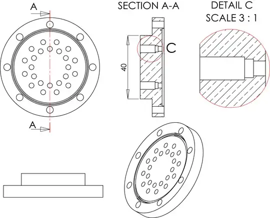
The existing design of the feedthrough flange is shown in the sketch below. The feedthroughs (single pin, weldable type feedthroughs made by Ceramtec) are not shown. They are installed into the holes that are highlighted in DETAIL C. The flange seperates the 1E-11 mbar extremely high vacuum (XHV) region from the outside, which is at ambient pressure.
During the important stages of the experiment, the vacuum vessel is submerged in LHe to cool it down to 4 K, which improves the vacuum to 1E-17 mbar and better. The thermal cycling is very demanding on the feedthroughs. (This is one of several reasons why commercial feedthrough flanges don't work for our purposes.)
The problem is: Does this design create virtual leaks?
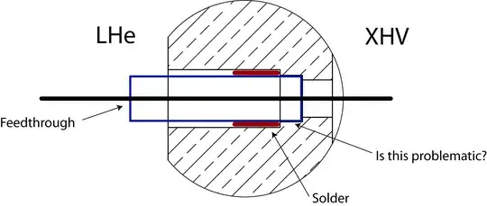
For reasons which might best be investigated in another question, we are soldering (not welding) the feedthroughs into the flange. When the feedthroughs are inserted into the holes, they sit quite snugly in the medium diameter hole. But because the solder is applied on the ambient-pressure side (marked as "LHe" in the diagram below), I fear that we are creating hard-to-pump pockets in the snugly-fitting "problematic" region.
The very first flange that was produced had the feedthroughs installed by silver-soldering them in a vacuum induction furnace at 800°C. This destroyed some of the feedthroughs, because they are not rated for 800°C. The destroyed (leaky!) feedthroughs were sealed using indium, but ultimately thermal cycling led to the leaks reopening, and the flange had to be discarded. However, for the 1-2 years that it worked, we had really great vacuum conditions below 1E-17mbar.
The current flange, which has the feedthrough soft-soldered (under standard atmospheric conditions), has no leaks to the outside. But judging from the limited lifetime of C$^{4+}$ ions, the best vacuum we get is only 1E-15mbar - 1E-16mbar. After eliminating many other possible culprits, virtual leaks from the hard-to-pump "problematic" region are the most likely explanation.
The possible workaround would be to reverse the direction of the holes in the design (smallest diameter on LHe, biggest on XHV side) and to apply the soft-solder on the XHV side. But I noticed that similiar experiments use the same design as we did, i.e. they apply the solder on the LHe side. The few people that I talked to about this could not recall why.
For welding, the rule of thumb is to always weld on the vacuum side. Is there any such rule for soldering?