0

I have a problem where I'm given a circuit that looks like:

enter image description here

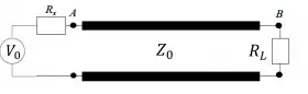
It contains a transmission line with a characteristic impedance $Z_0$, a source resistance of $R_s$, and a load impedance of $R_L$.

If the voltage source provides a constant DC voltage source of $V_0$, what are the voltages at points A and B?

I was considering using the voltage divider equation, but I don't think that's the right approach.

71GA
  • 2,633

3 Answers3

1

don't outsmart yourselves. If this is a DC problem, and the bottom node of the voltage source is assumed to be ground, the simple equation for voltage division is guaranteed to work. The characteristic impedance doesn't come into it.

This is not an abstract problem for me. I put DC through transmission lines all the time-- sometimes in combination with radiofrequency and sometimes by itself. And no, the question of how long the DC has been on (is it really DC?) doesn't enter the problem in any realistic scenario. Trust me, I am not a student, and have been doing this sort of thing for thirty years.

If you want, you can look at this from the standpoint of transmission line theory, which will tell you that at sufficiently low frequency and long time, there is essentially no transformation of the load impedance.

0

Lets say on one the top of the supply $V_0$ you have the potential $+12V$ and $0V$ on the bottom side. Do you recall how is the voltage defined? It is the difference of the potentials soo lets take two potentials... one on the bottom of the supply and one in the point B.

I can calculate the voltage between point B and supply as the difference of those potentials:

$$V=V_B-0V = V_B$$

So in your case the voltage between a power supply and point B has the same value as the potential in point B. Now only one $Z_0$ and $R_L$ stand between those two potentials. You can calculate the rest yourself using current $I$ ;)

71GA
  • 2,633
0

The characterisitic impedance of a transmission line at any frequency is: -

$Z_0 = \sqrt{\dfrac{R+jwL}{G+jwC}}$

At dc, jwL and jwC have no part to play hence $Z_0 = \sqrt{\frac{R}{G}}$

The propagation constant for a transmission line at DC is $\sqrt{R\times G}$ and can be used in the following formula: -

$\dfrac{V_{IN}}{V_{OUT}} = e^{distance\times\sqrt{R\times G}}$

The same relationship holds for current in and current out too.

From this information you should be able to calculate the net resistance looking into the transmission line at point A and hence what the current is into node A and hence what the voltage at node A is.

It is quite tricky so good luck and if this doesn't help let me know and I'll give it another "think" tomorrow.

Andy aka
  • 256