Look at the integral
$$I=\int_{S}^{}\vec{J}\cdot\mathrm{d}\vec{S}\tag{1}.$$
For this to make sense, the surface $S$ should be orientable, that is, it should be possible to assign in a continuous way a normal unit vector $\hat{n}$ at each point of the surface. Once one has assigned this field of normal unit vectors, the scalar product $\mathrm{d}I = \vec{J}\cdot\hat{n}\,\mathrm{d}S$ at each point can be either positive or negative, and so the integral $I$ which is the sum of all the $\mathrm{d}I$’s. However, for a given orientable surface $S$, there are two possible orientations, which can be chosen arbitrarily. Therefore, depending on the chosen orientation, $I$ can have either sign.
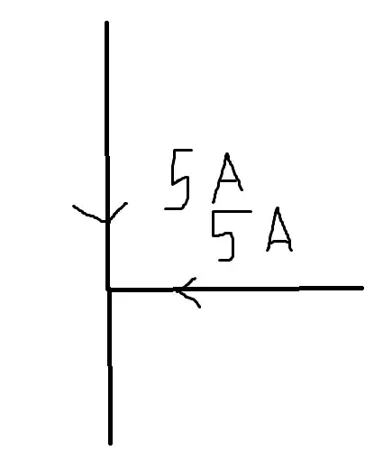
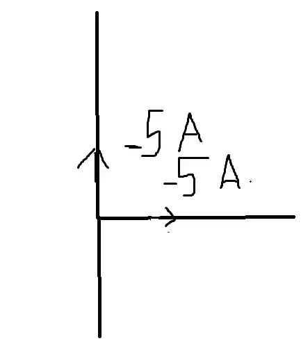
When you assign a reference direction to a wire or a component in a circuit by means of an arrow, you’re actually assigning an orientation to the surfaces crossing the wire that can be used to calculate $I$ with (1). If you reverse the reference direction, $I$ changes sign.
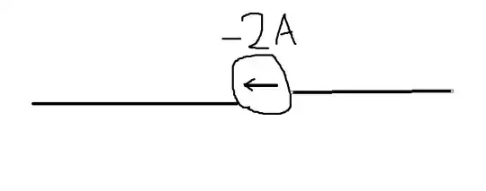
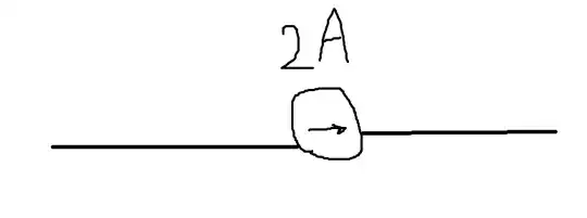
For instance, in the case of the first circuit with the current source, the reference direction for that source is specified by the arrow in the circle, and the minus sign on the current simply means that the integral (1), with the $\mathrm{d}S$’s oriented in agreement with the arrow, is negative. In the second circuit the arrow specifying the reference direction is reversed, and thus $I$ changes sign if the vector field $\vec{J}$ is the same.
