2

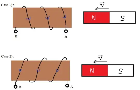
In Case 1) and Case 2) (see the image below) induced current is flowing counterclockwise (from the magnet's POV) if we move the magnet towards the coil (and the circuit is closed, obviously).

However I'm not so sure about the direction of the induced voltage. Can you please explain to me that in Case 1) and Case 2) which end of the coil will be more positive, A or B?

enter image description here

Thanks for the explanation in advance!

Side note: This is a question I asked at Electrical Engineering StackExchange, but nobody there could answer it, so I guess it is more related to Physics.
gvg
  • 25

4 Answers4

3

You have already figured out in which direction the current flows. In both cases the current produces an electromagnet whose north pole is facing the north pole of the approaching bar magnet. So both magnets repel each other, in accordance with Lenz's law.

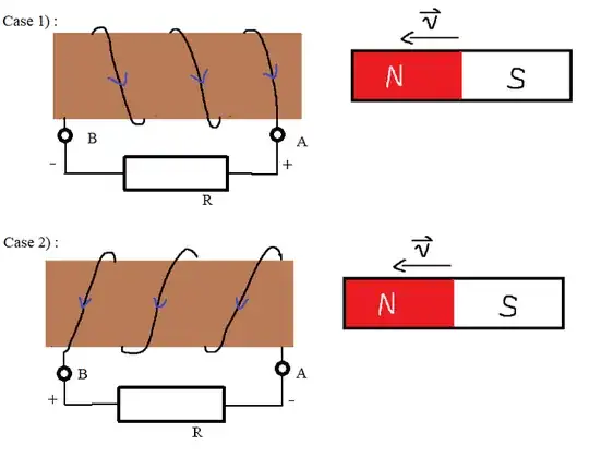
The fact that a current flows at all, implies a closed circuit. Therefore I have drawn a resistor $R$ between the points A and B, thus closing the circuit. Then you can figure out the voltage by Ohm's law.

enter image description here

In case 1 the current flows through the resistor from right right to left. This gives you the voltage across the resistor: positive on the right, negative on the left.

In case 2 the current flows through the resistor from left to right. This gives you the voltage across the resistor: positive on the left, negative on the right.

2

A variating magnetic flux through a coil creates a voltage in a concrete direction of rotation. I don't know from memory if the north pole makes it one way or the other, but the important thing is that it's always the same direction of rotation (given by Maxwell laws): \begin{equation} \nabla \times E = - \frac{dB}{dt} \end{equation}

(In the picture you have, assuming the rotation direction is right, seems that the magnet generates a counter clock-wise current if you look at the coil from the magnet's perspective)

So obviously the current will flow towards the magnet or away from it depending on how you wind your coil! The only fixed thing is the direction of rotation of the current :)

1

Consider Case 1) with a voltmeter (resistor) connected across terminals $A$ and $B$.
The current though the voltmeter will pass from terminal $A$ to terminal $B$.
For a resistor the current always passes from a point of high potential to a point of lower potential thus the potential of $A$ is higher than that of $B$ and the reading on the voltmeter would show that to be the case.

Your confusion might be due to the fact that the coil is a source of (induced) emf.
Inside a battery the current flows from the negative terminal to the positive terminal driven by the electrochemical reaction within the battery.
Within the coil it is the change of magnetic flux which is ultimately driving the current from terminal $B$ to terminal $A$ and that is the direction of the induced emf.

Farcher
  • 104,498
1

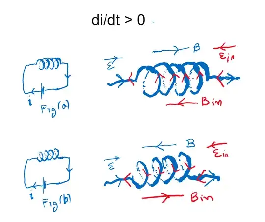
Winding direction does not affect the direction of the self induced emf of an inductor. In the image shown below, an inductor coil is wound differently (fig(a) and fig(b)) and connected to a battery sending the current left to right. And the current is increasing (di/dt >0) to produce induction in the coil. Since Eind = - L (di/dt) and Eind must be in the opposite direction to E from the battery. It is the case in both situation, doesn't depend on the direction of the coil winding. enter image description here