I came across a capacitors problem that seemed to be very simple, but I can't figure reasoning as to why two approaches to the problem yield two different answers. One of them is wrong, but I can't tell why.
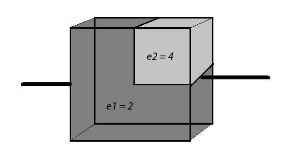
So in the figure above, consider the two faces of the cube connected by the wires as parallel plates of a capacitor, each with area $A$. It is filled completely with two materials of dielectric constants $\epsilon_1=2$ and $\epsilon_2=4$. The side length of the cube is $d$. Now, I thought of two ways to 'break' the system, as below:
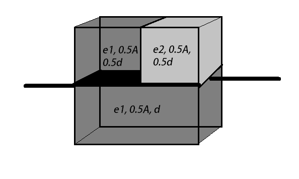
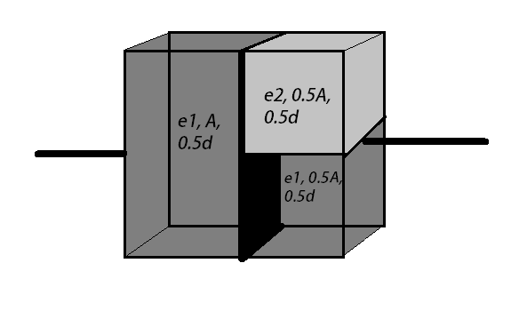
The first figure is the correct way of doing the problem, and after calculating the capacitances of each individual block, and finding the net capacitance, the answer comes out to be $\frac{7A\epsilon_0}{3d}$. The second figure is what I thought could be another way of solving the question, but it yields a very different answer of about $\frac{12A\epsilon_0}{5d}$. And I cannot tell why.
The reason could be that the potential of the face where I am making the partition in the second figure is not the same for both blocks (the ones to the right), so assigning them a parallel combination is an error. But I can't tell why the potential should be different. The charge is flowing to those blocks in a very uniform way from the left, they can't be at a different potential.
Original question from JEE Advanced 2015 paper 2
Apologies if the figure is a bit sketchy, I tried my best to recreate it as I could not find a clear image of the problem on the internet.
Edit: In the first figure, the two blocks at the top are in series and the bottom block is in parallel combination with them. In the second figure, the two blocks at the right are in a parallel combination, and the block at the left is in a series combination with them.