Imagine two poles of a battery to be one meter separated from each other. We connect the poles with a conducting wire after which a current flows. Can we stop the current from flowing by placing the battery between two large charged parallel plates? If so, how high must the voltage between the plates be compared to the voltage of the battery?
I know that a static electric field can't penetrate a metal. But what will be the case if a current flows through it?
- 1
- 5
- 45
- 105
3 Answers
Can we stop the current from flowing by placing the battery between two large charged parallel plates?
No.
[I am assuming that the wire is not in electrical contact with the plates. Perhaps there are holes in the plates for the wires to pass through, or alternatively, the wire enters the cavity between the plates from the sides, then turns perpendicular to the plates, and then again, exits through the side. One final arrangement is that the entire circuit is in the cavity between the plates. The result is the same for all three configurations as long as the wire is not in electrical contact with the plates.]
As the voltage across the plates is increased, the wire will develop charges at the points of nearest approach to the plates. [That is, the electrons in the wire, will re-arrange themselves]. These charges will be opposite to the charges in the plate. They will create a $\vec{E}$ field in the wire equal and opposite to that created by the plates in the wire. The net effect will be that the emf applied by the battery will drive the same current through the wire with or without charges on the plates.
[On a side note, the electric field between two plates with nothing but a dielectric between them appears as parallel lines (with some fringing at the sides) as drawn in the original question. However, the electric field between two plates with a wire between them, even though not electrically connected, will be substantially different, whether or not there is current flowing through the wire.]
- 3,825
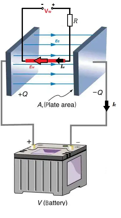
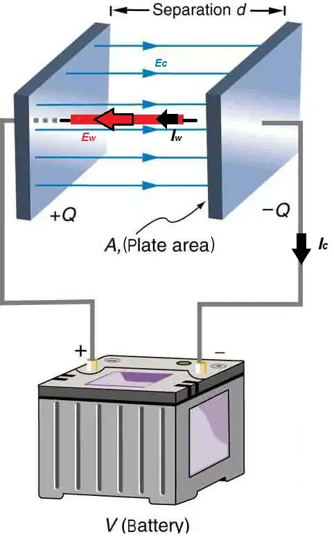
Assuming a straight electrical wire with no dielectric insulation (i.e. dielectric constant of wire insulation would reduce the displacement Ec field of the capacitor), positioned perpendicular to the plates of the capacitor as shown in the figure and provided, also that the wire is powered by a different source than the capacitor and the capacitor is fully charged, then the short answer is ideally,
when Ec(inside wire)=-Ew (Eq.1)
where Ec(inside wire)≠Ec (i.e. Ec value in vacuum)
The two electric fields Ec(inside wire) of the capacitor and Ew of the voltage source Vw inside the wire will cancel out and no electric current Iw will flow through the wire.
Practically, this means that you must make sure that the polarity (+/-) of the source powering the wire is opposite to the polarity of the voltage source V powering the two plates of the capacitor and quantitatively that the displacement current between the capacitor plates is made equal and opposite sign of the d.c. current Iw flowing through the wire thus,
Ic(maximum peak)=-Iw (Eq.2)
The displacement current between the plates of a fully charged capacitor (i.e. when fully charged, current on the capacitor circuit lines is ideally zero Ic=0) is the maximum peak value measured of Ic current at the beginning of the capacitor charging period.
Meaning that you have to choose the correct value of source voltage V for your capacitor circuit that would cancel out the current on the wire Iw.
You could do a theoretical calculation but it would be complicated with a possible large error bar, knowing the exact resistivity and impedance values of the two circuits but if your question is related to a practical application and assuming your capacitor in the circuit is fast charging, you could just keep increasing V voltage value until you measure Iw=0.
Updated figure added 14 May 2021: Because it seems that there is a lot of confusion created about the previous figure also seen in this answer, I have added a second version of the circuit schematic that I hope will clarify things. The conventional flow of current is used.

Answer update added 22 May 2021: The electric field Ew inside a current carrying wire connected to a voltage source is not zero. The E=0 case inside a conductor holds only for Electrostatics and not for a current carrying conductor where the electric field inside the conductor is not zero, E≠0. The whole point of this circuit is that the naked wire (marked as red) inside the field of the capacitor is connected to a voltage source therefore electrostatic equilibrium is continuously disturbed and never reached. physics.stackexchange.com/a/250651/183646 There is definitely Ew present opposite to Ec all the time after the capacitor is charged. We can assume the capacitor is in vacuum to avoid dielectric leakage and therefore an ideal case. The fields will interact and therefore affect the current on the wire. Of course because the huge difference of conductivity between the air and the wire a huge voltage Vc would be needed on the plates of the capacitor to zero even a small current on the wire Iw.
The system operation is not linear. Putting Vw at 0 results to electrostatic equilibrium and surface charge on the wire with the electric field inside the wire Ew=0. However, putting Vw to any non-zero value gives Ew≠0 inside the wire. Therefore you cannot superposition for Vw=0. Things are more complicated, https://link.springer.com/article/10.1023/A:1018874523513 , https://www.if.ufrj.br/~dore/Fis3/Assis_et_al.pdf .
I am not saying that my answer is 100% correct and it is assuming ideal case. However after further investigation things seem more complicated and unless an exact analytical solution to the problem is given or a related experiment is presented I regard this question a big question mark!
Answer update 28 May 2021: https://tinyurl.com/2ca5byv7 There is a experiment done by Oleg Jefimenko showing clearly the axial homogeneous electric field formed inside an d.c. electric current carrying wire. The question now is will the electric homogeneous vectors inside the wire of this field interact with the electrostatic aligned field of the capacitor?
Final answer update 29 May 2021:
Except the case of Vw=0 where there is electrostatic Equilibrium and Ew=0 inside the wire and therefore the operation of our system is not linear compared with all other values of Vw≠0 where there is an electric field created inside the wire due the current Ew≠0 by the Vw voltage source and there is no electrostatic equilibrium formed on the wire that can repel an external electrostatic field and thus the case Vm=0 cannot be used in the analysis, then,
"Electric fields are fully described by Maxwells eqs, which are linear in both E and B. Linearity implies superposition, which means that the fields do not interact with each other, but simply add vectorially. If they have equal and opposite amplitudes at any point, the resultant will be zero - i.e.exact cancellation at that point. That is true for both static and time/spatially varying fields." [https://physics.stackexchange.com/a/411049/183646]
Therefore my initial answer is correct .
- 4,572
The answer by @Markoul11 is incorrect and the answer by @Math Keeps Me Busy is correct. The easiest way to analyze this problem is to use the principle of superposition as follows:
Both Maxwell’s equations and the equations of circuit theory are linear. This means that you can find the total current through the wire by simply finding the current due to each source individually and summing them.
To get rid of a voltage source we simply give it a voltage of 0. And in all cases we are considering the voltage source (a battery) to be operating at DC steady state.
Setting the external voltage source to 0 and the connected source to $V_{\text{connected}}$ can be analyzed with the usual circuit theory, and gives the standard Ohm’s law current. So in this case there is a current in the wire and a linearly changing voltage inside the wire, and a surface charge which produces the correct field distribution inside the wire. https://doi.org/10.1119/1.18112
Setting the connected source to zero and the external source to $V_{\text{external}}$ cannot be analyzed with circuit theory, but is easy to analyze with Maxwell’s equations. The $V_\text{connected}=0$ "short circuits" that connection, giving a closed conductive loop. Since it is DC steady state this is a simple conductor in an external electrostatic field. A surface charge is induced on the loop and the current is zero. Importantly, the surface charge opposes the external field so that there is no field inside the conductor. So in this case there is no current inside the wire and no voltage inside the wire, just an external surface charge canceling out the external field.
Once we have analyzed each source independently we can simply add the two results together to determine the current from both sources together. So when both $V_{\text{external}}$ and $V_{\text{connected}}$ are on we have the non-zero current from the connected source added to the zero current from the external source to produce a non-zero current. We also have the non-zero internal voltage gradient from the connected source added to the zero internal voltage from the external source to produce a non-zero internal voltage gradient. Finally, we have the non-zero surface charge distribution from the connected source and also the non-zero surface charges from the external source added to produce a non-zero total surface charge distribution. In summary, the external source produces 0 current and cannot stop the current from the connected source. Its effect is solely to alter the usual surface charge distribution on the wire.
- 117,350
