I assume you're asking about compression or elongation of this structure along the primary helical axis.
Let's first look at the standard helical spring model, which translates axial spring deflection into torsion of the bulk material:
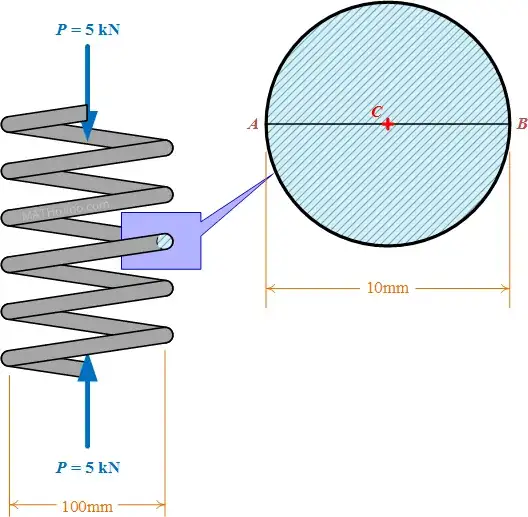
For simple torsion, the relationship between the twist angle $\theta$ and the torque $T$ for a circular cross section of radius $r$ is
$$\theta=\frac{2Tl}{\pi G r^4}$$
where $G$ is the shear modulus and $l$ is the length of the rod. This model forms the basis for the simplest calculations of the spring constant of a helical spring, as the torque $T$ is coupled to the end load $P$ by $T=PR$ (where $R$ is the radius of the helix, or half the width of the spring) and the rod length $l$ is coupled to the spring length $L$ by $L=2\pi NR$, where $N$ is the number of coils. We end up with a spring constant $k$ of approximately
$$k=\frac{P}{x}=\frac{Gr^4}{4NR^3},$$
where $x$ is the spring deflection.
Now, however, with the second level of helicity, compression involves torsion applied not to a circular cross section of bulk material but to the smaller helix. This now involves either elongating or compressing the bulk material, not shearing it. In other words, the problem can be transformed into uniaxial strain of a long, thin rod (or bar or wire), which depends only on the cross section and length (which can be calculated from the geometry) and on Young's modulus. Since twisting a helix by an angle $\theta$ gives end motion of $\theta r$ (for radius $r$), corresponding to axial deformation of the rod of length $2\pi n r$, where $n$ is the number of turns of the smaller helix, the required axial strain is
$$\varepsilon=\frac{\theta}{2\pi n}=\frac{F}{AE},$$
where $F=T/r$ is the axial force on the rod, $A$ is its cross-sectional area, and $E$ is Young's modulus. This corresponds to a modified spring constant $k^\prime$ of
$$k^\prime=\frac{AE}{2\pi n R}$$
for this extensional mode. Note that additional deformation modes also play a part; as described in the link above, the external load on the spring also induces bending of the helix, for example. This must be analyzed separately.

