2

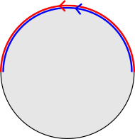
In Nakahara section 4.9, "Defects in nematic liquid crystals", it is discussed that the order parameter for a nematic should be the real projective plane $\mathbb{R}P^2$, which has fundamental group $\pi_1(\mathbb{R}P^2) \cong \mathbb{Z}_2 = \{0,1\}$. The real projective plane's fundamental group is generated by two homotopy classes, one being a trivial loop and the other a non-trivial loop which winds around the space. As discussed earlier in the text, the fact that the fundamental group is isomorphic to $\mathbb{Z}_2$ is equivalent to the fact that winding around the non-trivial loop twice creates a trivial loop, as demonstrated in this represetation, where antipodal points of the disk's boundary are identified:

enter image description here

Correspondingly, it is then stated that there are two types of line defects in a nematic, one of which can be deformed to a uniform configuration and one which cannot. These are shown in the following two figures,

enter image description here

enter image description here

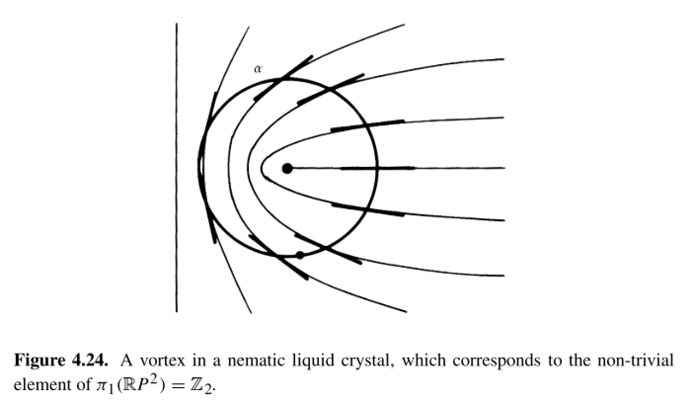
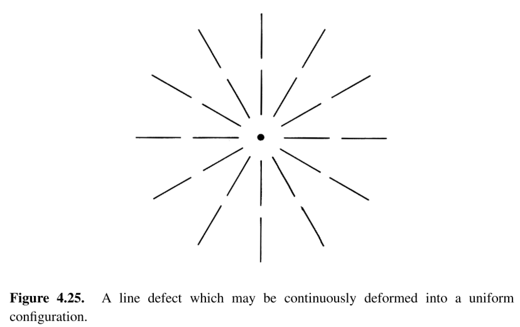
However, I am having trouble visualizing how the configuration in 4.25 can be deformed to a uniform configuration. I was trying to visualize it in the same way as in Figure 4.16: take a circle $S^1$ surrounding the line defect (like the curve $\alpha$ in 4.24) and think of how it maps into a curve on $\mathbb{R}P^2$ ala Figure 4.16, but have thus far I am still very confused as to how to visualize the deformation in 4.16 in terms of the configuration shown in 4.25.

Can anyone explain how the deformation should be done and how it relates to the deformation in 4.16? And for that matter, how the configuration in 4.24 maps into $\mathbb{R}P^2$?

Qmechanic
  • 220,844
Kai
  • 3,930
  • 1
  • 15
  • 29

1 Answers1

1

I think your confusion stems from the fact that the drawings are only 2D spatial projections of a three-dimensional nematic liquid crystal. In 2D, the order parameter space would be $\mathbb R P^1$ which is isomorphic to the circle $S^1$. In this case, the defects would be point defects classified by $\pi_1(S^1) / \{ n \sim -n \}$ and both defects would be stable under continuous deformation, with winding number $1$ and $2$ for Fig. 4.24 and Fig. 4.25, respectively.

However, for a 3D nematic liquid crystal the defects are line defects. If we consider a sideways view of the line defect of Fig. 4.25 it becomes obvious how to deform the configuration without affecting the boundary:

Continuous deformation of line defect to uniform configuration.

What does this correspond with in order parameter space? I will take the disk with antipodal points on the boundary identified $D^2 / \{ \mathbf r \sim - \mathbf r, |\mathbf r|=1\}$ to represent the real projective plane $\mathbb R P^2$. If we assume the director lies in the $xy$ plane then the loop $\alpha$ in Fig. 4.24 runs along the boundary of the disk:

Loop in configuration space corresponding to Fig. 4.24.

Note that this is a loop since the points $(1,0)$ and $(-1,0)$ are identified. Similarly, we have for Fig. 4.25:

Loop in configuration space corresponding to Fig. 4.25.

where the total loops consists of first going around the red loop and then going around the blue loop. Now, keeping the base point $(1,0) \sim (-1,0)$ fixed, we can deform the loops as follows:

Continuous deformation of the loop corresponding to Fig. 4.25.

Now one can contract the total loop as in Fig. 4.16. Note that this is not possible for the liquid crystal in two spatial dimensions, where there is no interior. Also note that points in the interior correspond to directors that point out of the $xy$ plane. Hence, we are performing the deformation shown in the figure above.

Praan
  • 1,167