3

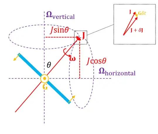
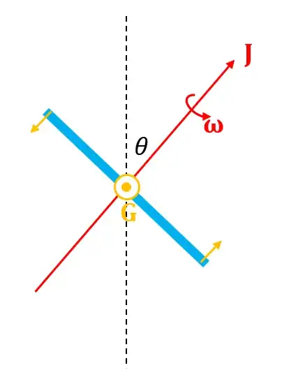
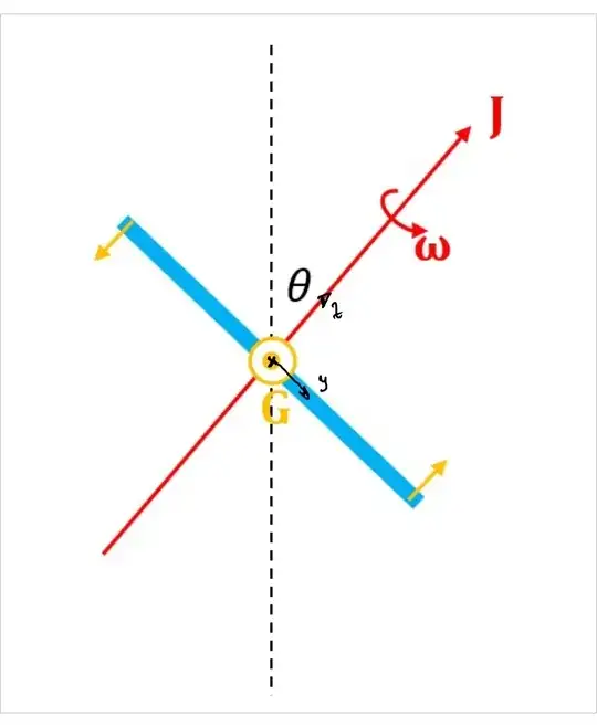
I'm calculating the (instantaneous) rate of precession of a symmetric top (i.e. $I_1=I_2\neq I_3$) that is tilted at angle $\theta$ to the vertical if a torque $\vec{G}$ is applied, as shown below:

gyroscope 1

It has initial angular velocity $\vec\omega$ about the 3rd principal axis, and initial angular momentum $\vec{J}$ about the same axis. The torque vector, $\vec{G}$ is coming out of the screen.

By adding $\delta \vec{J}=\vec{G}\;\delta t$ to $\vec{J}$, I can see that the angular momentum vector is going to move in a direction coming out of the screen. However, I don't know how to rationalise where it's going to go next - is it going to precess about the vertical axis or the horizontal axis? Why would it prefer one or the other? The precession frequencies in each case would be $$\Omega_\text{vertical} = \frac{G}{J\sin\theta}\;\;\;\;\;\;\;\;\;\Omega_\text{horizontal}=\frac{G}{J\cos\theta}$$ See figure below: gyroscope 2
EDIT: For context, I am trying to find the precession of the Earth due to the Sun alone. I am modelling the Earth as a symmetric top exactly as above, and the torque comes from the tidal forces on the Earth from the Sun. I have already calculated the properties of the disc and the torque, I am just stuck on rationalising why the angular momentum vector (i.e. the South -> North vector) should rotate about an axis perpendicular to the Earth-Sun radius, rather than parallel to it). I think the question remains the same.
Garf
  • 2,486

2 Answers2

1

The answer has been given in the comments, but here it is more fully.

When an angular momentum $\bf J$ changes direction, it is owing to a torque $\bf G$. The equation of motion is $$ {\bf G} = \frac{ {\rm d} \bf J}{{\rm d} t} $$ In the case of precession, one has a torque $\bf G$ whose direction changes as $\bf J$ does. For example, for a spinning top resting on a horizontal floor, the combination of gravity and the normal reaction from the floor makes the torque always perpendicular to $\bf J$ and parallel to the floor. We need both these properties to fix the axis about which the precession happens. The axis has to be perpendicular to the floor in this example.

In the case of Earth and Sun there are two aspects to think about. To first approximation there is no torque at all, because if we treat Earth as a rigid body the Sun's gravity acts through the centre of mass, and the orbital motion balances that. That is, in a frame attached to the Earth there appears a centrifugal force which is just strong enough to balance the Sun's gravity $G M m/r^2$ so that the Earth does not accelerate in this frame, but both forces act through the centre of mass, making no net torque.

Then, as was said in the comments, the tidal effect comes into play, as the Sun's (and Moon's) gravity gets to grips with the Earth's equatorial bulge. These effects give further forces whose direction produces torque parallel to the plane of the orbit, trying to 'right' the tilt of the Earth. Therefore the axis about which precession happens is perpendicular to the plane of the orbit.

To summarize, the answer to the question is all about the way the direction of the torque evolves as the angular momentum does. In particular, if the torque is always parallel to the plane of the orbit, then the component of angular momentum perpendicular to the plane of the orbit is a constant of the motion.

Andrew Steane
  • 65,285
1

enter image description here

I try to write the equations of motion for your case, starting with the rotational matrix

$$R=R_x(\theta)R_y(\beta)R_z(\Omega\,t)\tag 1$$

where $\Omega$ is the earth rotation and t the time

$$R_x(\theta)=\left[ \begin {array}{ccc} 1&0&0\\ 0&\cos \left( \theta \right) &-\sin \left( \theta \right) \\ 0& \sin \left( \theta \right) &\cos \left( \theta \right) \end {array} \right] $$ $$R_y(\beta)= \left[ \begin {array}{ccc} \cos \left( \beta \right) &0&\sin \left( \beta \right) \\ 0&1&0\\ -\sin \left( \beta \right) &0&\cos \left( \beta \right) \end {array} \right] $$ $$R_z(\Omega\,t)=\left[ \begin {array}{ccc} \cos \left( \Omega\,t \right) &-\sin \left( \Omega\,t \right) &0\\ \sin \left( \Omega\,t \right) &\cos \left( \Omega\,t \right) &0\\ 0&0&1 \end {array} \right] $$

The Euler equation:

$$\Theta\,\vec{\dot{\omega}}+\vec{\omega}\times \left(\Theta\,\vec{\omega}\right)=\vec{\tau}\tag 2$$

where $\Theta$ is the inertia tensor and $\vec{\tau}$ auxiliary torques :

$$\vec{\tau}=\begin{bmatrix} G \\ 0 \\ 0 \\ \end{bmatrix}$$

with equation (1) you get the angular velocity (the components are in body fixed frame).

with: $\dot{R}=R\,\tilde{\omega}$, where $\tilde{\omega}$ is a skew matrix

$\Rightarrow$

$$\vec{\omega}=J_R\,\vec{\dot{q}}= \left[ \begin {array}{cc} \cos \left( \beta \right) \cos \left( \Omega\,t \right) &\sin \left( \Omega\,t \right) \\ -\cos \left( \beta \right) \sin \left( \Omega\,t \right) &\cos \left( \Omega\,t \right) \\\sin \left( \beta \right) &0 \end {array} \right] \,\begin{bmatrix} \dot{\theta} \\ \dot{\beta} \\ \end{bmatrix}+\left[ \begin {array}{c} 0\\ 0\\ \Omega\end {array} \right] \tag 3$$

with the generalized coordinates vector $\vec{q}=\left[\theta\,,\beta\right]^T$ we can obtain with equation (3)

$$\vec{\dot{\omega}}=J_R\vec{\ddot{q}}+ \frac{\partial\vec{\omega}}{\partial\vec{q}}\vec{\dot{q}}+\frac{\partial\vec{\omega}}{\partial t}\tag 4$$

with $\vec{\dot{\omega}}$ equation (4) and $\vec{\omega}$ equation (3) in equation (2) you get the equations of motions for the generalized coordinates $\vec{\ddot{q}}$

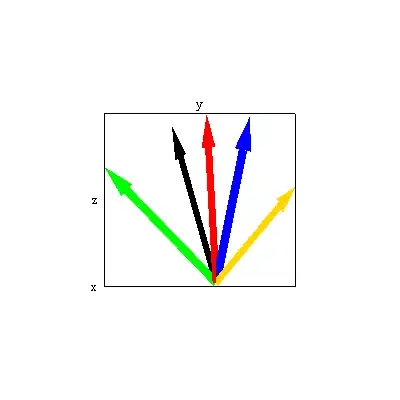
Simulation results

1) blue arrow is the start position of z axis

2) red arrow

3) green arrow

4) gold arrow

5) final position black arrow

enter image description here

Eli
  • 13,829