12

There's a bit of furore from this question on Youtube involving Dr. Walter Lewin and another Youtuber. With Dr. Lewin claiming Kirchhoff's Law doesn't always hold when magnetic fields are involved, and that two voltmeters attached to identical places in a circuit can give different readings. Is this the case?

Original Video : https://www.youtube.com/watch?v=0TTEFF0D8SA

Dr. Lewin's response : https://www.youtube.com/watch?v=AQqYs6O2MPw

Qmechanic
  • 220,844

2 Answers2

8

...claiming Kirchhoff's Law doesn't always hold when magnetic fields are involved, and that two voltmeters attached to identical places in a circuit can give different readings. Is this the case?

It is true that two voltmeters connected to same pair of points in a circuit can show different values. The reason is the voltmeters can be affected differently by induced electric field, because this field is non-conservative (it has non-zero line integral over a closed path); this induced electric field is present because there is a changing magnetic flux.

What is the point of contention here between prof. Lewin and his opponents is terminology(semantics) of the words like potential and voltage.

As others on this site have observed, whether KVL is applicable depends on:

  • which version of KVL we use: there is the historical version about sum of electromotive forces in a circuit, and there is the modern textbook form about potential drops along a circuit;

  • what we mean by voltage (or electromotive force, if we use the original version of KVL).

Prof. Lewin seems to understand voltage as either 1) integral of total electric field along some path connecting two points; or 2) whatever voltmeter connected to two points shows. In both cases, his voltage is ambiguous, as it depends either on the chosen path of integration in space, or on how the probes of the voltmeter are arranged in space. With voltages defined as integrals of total electric field, the modern KVL indeed does not hold, because their sum equals minus net electromotive force for the circuit and this emf is arbitrary, depending on how we arrange the integration paths (or wires).

But the textbook authors claiming/implying that KVL holds for such situations with changing magnetic flux are not wrong, because in KVL, the concept of voltage between two points is that it is difference of electric potentials of those points, irrespective of whether a voltmeter or other device can measure it. This is a prevailing convention in the context of KVL and circuit theory because:

  • electric potential can always be naturally and uniquely defined as the potential of the conservative part of the electric field, i.e. the Coulomb-integral potential of all charges around, even in high frequency AC circuits with solenoidal fields everywhere (such potential is less useful in such high frequency cases but there is no problem in its definition)

  • this definition is very useful in lumped elements model of circuit, because then each pair of terminals in a circuit has unique potential drop, equal to difference of Coulomb potentials on those terminals.

With prof. Lewin's implied definition (integral of total electric field), we would encounter various problems. For example, line integral of electric field taken along a path connecting two terminals of an ideal solenoid in which electric current is changing would be arbitrary, dependent on the chosen integration path. It could always be made zero if the path is chosen to be entirely inside the perfect conductor the solenoid is made of. Thus without restricting the path in some way, the definition gives no definite value of voltage for the inductor and we could not use the usual tools of analysis for lumped element model like KVL.

Of course, the standard circuit theory asserts that voltage (to be used in KVL) on ideal inductor is unique: $$ p.d.(ideal~inductor) = L\frac{dI}{dt}. $$ This cannot be understood as integral of total electric field (which would depend on the choice of path). Instead, it is integral of electrostatic part of it (which does not depend on that choice), or equivalently, minus electromotive force inside the solenoid - the "solenoidal component of electric field" or the "induced field" integrated along the path that is entirely in the wire of the solenoid.

2

I believe there should be an answer that showcases the advantages of the other version of voltage, so here it goes...

No, KVL does not always hold. If you extend the definition of voltage given in the electrostatic case to the more general dynamic case, that is if you define voltage as the line integral of the electric field (in accordance to ISO and IEC - two of the most important global standard organizations), $$ V_{\gamma_{A \to B}}= - \int_{\gamma_{A\to B}}\vec{E} \cdot d\vec{\ell} $$ then "voltage" and "potential difference" have different meanings since, when we decompose the electric field into its irrotational and solenoidal components ($ \vec E = - \vec \nabla \phi -\partial \vec A/\partial t $), we get

$$ V_{\gamma_{A\to B}}= \int_{A}^{B}\vec{\nabla}\phi \cdot d\vec{\ell}+\int_{\gamma_{A\to B}}\partial{\vec{A}}/\partial{t}\cdot d\vec{\ell} \\ = (\phi_B-\phi_A) +\int_{\gamma_{A\to B}}\partial{\vec{A}}/\partial{t}\cdot d\vec{\ell} $$

This 'version' of voltage is in general path dependent and is composed of a scalar potential difference (which is the path-independent part to which Kirchhoff's loop law always applies) and a path-dependent induced voltage component. Beside complying with worldwide accepted standards, there are more cogent reasons to adopt this definition of voltage, namely:

  1. This voltage is the measurable quantity that happens to be what a voltmeter measures.
  2. This voltage is the physically relevant quantity that happens to be gauge invariant.
  3. This voltage does not require you to simultaneously specify another quantity (such as the magnetic vector potential A in space or 'the partial EMF' in the circuit) to completely describe the state of your circuit (ceteris paribus).

Moreover,

  1. This voltage does not lead to contradictions when you try to apply Ohm's law (such as "you can't apply Ohm's law to the coils of an inductor or transformer" or "a resistor does not always drop a 'voltage' equal to its resistance times the current flowing through it").
  2. This voltage does not change with (slowly varying) changing magnetic fields outside of your circuit and outside of your measurement loops.

The price to pay for the above advantages is that we have to deal with a path-dependent quantity that can assume more than one value when there are relevant time-varying magnetic field linked by either the circuit or the measurement loop. But wait: even if it is in general multivalued (because somewhere there are always variable magnetic field) this voltage can be single-valued in all simply connected regions of space that do not contain such fields.

This is why in lumped circuit theory it is required that all changing magnetic fields be confined inside the magnetic components (see the celebrated section 22-7 on the second volume of Feynman's Lectures - or any good circuit theory textbook) : if this condition holds, then the circuit path - which will presents jumps at the terminals of the magnetic components - can be made dB/dt free and all voltages between any two points on this path will be single valued.

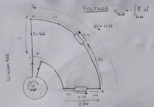
Here's the difference between using voltage (as the line integral of the total electric field) and scalar potential difference (the line integral of the conservative part of the the electric field) in the case of an AC powered circuit. The source of magnetic induction is supposed to be an infinitely long circular solenoid with a single turn EMF of 1Vrms. Using voltage gives the usual values we expect from lumped circuit theory:

AC circuit using voltage

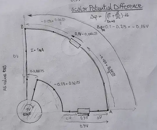
But if we choose to use the scalar potential difference, we get values that are inconsistent with Ohm's law and in general would require a numerical integration depedening on the shape, position and orientation of the circuit with respect to the source of magnetic induction:

AC circuit using scalar potential difference

Things get even weirder if we have a DC powered circuit just sitting next to a source of magnetic induction, without even linking it. This is the strange state of affairs when using the scalar potential difference:

DC circuit near a non-linked AC source using sPD

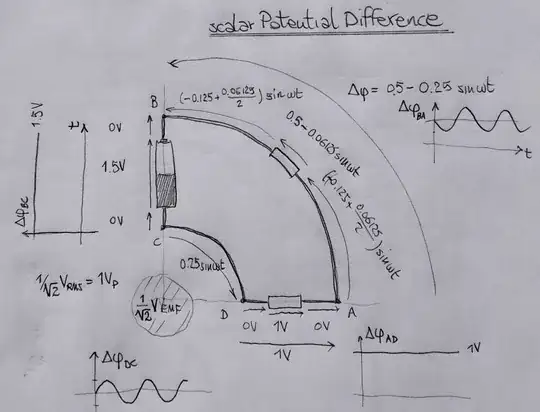
We get time-varying (scalar) potential differences in a DC circuit! This is not something you see in any circuit theory textbook. Using the scalar potential difference as synonym of voltage in circuits near sources of magnetic induction can only cause unnecessary complications.
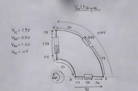
On the other hand, if we choose to use voltage we get the ordinary value we would expect in a DC circuit:

DC circuit near a non-linked AC source using voltage

I have a few more examples that illustrate the remaining points. Maybe another day...

Peltio
  • 906