I saw this arrangement for tensioning overhead cables from my train window (schematic below). Why not just have one pulley wheel leading directly to the weights? What function do the additional pulleys serve? For that matter, what are the cables for? They're clearly not power lines.
5 Answers
Having more pulleys increases the mechanical advantage of the system. In this case the mechanical advantage is 3. This means that the weights involved need to be a third as massive and the cables passing over the pulleys need to have a third the strength. This makes everything cheaper, smaller, and more tractable: it means, for instance, that you can use cheap, rather low-density, materials for the weights (they are often piles of concrete disks around a central metal rod). Cheap weights are both, well, cheap, but also less interesting to thieves: no-one wants to steal concrete disks, a lot of people want to steal lead, say, and metal theft is a big problem for many railways (obviously this part of the reason has no physics content, but it's important). Another reason for reducing the mass of the weights may be to do with how hard it is to install and maintain things: the lighter the weights are the less heavy machinery you need to get close to them. I don't know to what extent this is a consideration, and it's also not really a physics issues. Finally the pulleys can be a lot smaller as well as thin cables are more flexible.
In answer to the second question: yes these probably are the ends of the power lines (although there may be some big insulator out of the shot). I'm not an expert on railway power systems but I think what they tend to do is have overlapping sections of power cable, so at a mast one set terminates while the other set carries on (assuming anything ends at all there: a lot of the masts are just for support I think).
This is a so-called block and tackle arrangement which is often used for tensioning of overhead lines. Tensioning is required to keep a desired line geometry and, in case of contact wires, to avoid standing mechanical waves (waves in a tensioned line travel faster).
Apart from mechanical advantage, such systems often provide a safety braking mechanism which prevents the line from unravelling completely in case it breaks.
The location in your photo most probably corresponds to an overhead line section break: the power line on the left side has ended, was pulled outside of the tracks and terminated by a tensioning mechanism. About a hundred meters to the left, a new section must have started (probably with another tensioning mechanism) and pulled to the middle of the track at the point where the photo is taken. That's the wire you see just above the mechanism in question.
- 4,845
Railway overhead electrification is a complex business, I am far from an expert but this is my simplified understanding.
There will normally be at least two wires, a "contact" wire which runs horizontally to make contact with the train's pantograph and a "catenary" wire which supports the contact wire. An appropriate tension must be maintained in the wires, too tight and the stresses from trains would be unacceptable, too loose and the wires would droop.
Wires contract and expand with temperature, this implies two things.
- A tensioning system is needed that can maintain tension as the length of the wires changes.
- The distance between tensioning points is limited. Otherwise distortions to the geometry from expansion and contraction would become unacceptable.
So periodically along the length of the railway the wires will pull off to a tensioning device at the side (or sometimes overhead). There will be an overlap between sections of wire so there is always a wire to hold the pantograph in place.
In this case the tensioning device consists of three pulleys and a set of weights, the pulleys will reduce the weight needed to achieve the desired tension in the wires. Then there appears to be an insulator and then a bar joining the catenary and contact wires.
- 1,181
You already got an answer to your main question - why are there pulleys? I will attempt to answer the second question - what is this wire?
There are two possible answers.
First, I found the following image at http://www.rail.co.uk/rail-news/ecml-suffers-another-failure/
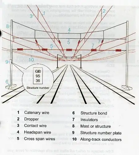
The label tells us that this is a "along-track conductor" pair. Such conductors may be used to distribute power over longer distances (without the power line rubbing against the pantograph - think of it as a parallel circuit). The cable expands and contracts with temperature which is why you need a tensioning mechanism with a lot of "play" (and which maintains constant tension, which a spring won't do quite as well - at least not as easily).
There is a lot of detail about overhead electrification in this document if you want to read more.
But then, I found another picture on this site - one that is almost identical to yours:
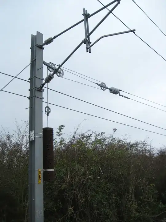
The caption says
Figure 11: Overhead line suspension system. The weights and pulley system is designed to maintain contact wire tension. Photo: Author.
The insulator is a bit more clearly visible in this picture, but it seems plausible that this is a picture of the same mechanism that you saw. That means this is indeed providing tension for the contact wire, which is the wire that the pantograph rubs against.
- 119,981
It's to maintain the tension in the overhead powerline. The line acts like violin string, with the collector on the train acting as a bow. If the train is travelling faster than the wave in the power line, then a standing wave may be induced in the power line, causing it to snap. The line will contract and expand with temperature, so a fixed load is placed on it. See the Wikipedia entry
- 109


