13

Consider a Photoelectric effect experiment apparatus as shown in Figure 11.1

Figure 11.1

The variation of photocurrent with the voltage applied across $\mathrm{A}$ and $\mathrm{C}$ is as shown in Figure 11.3.

Figure 11.3

My question –

Why is the current non-zero even if the voltage is zero?

Consider a situation in which the voltage across the plates is zero. Photons of sufficient frequency strike the outermost surface of the cathode, emitter plate $\mathrm{C}$. Electrons become free from the attraction of nucleus as their net energy becomes positive.

Why I think that there should be no net current?

As soon as photons strike the outermost surface of the cathode(assumed to be $1$ to $10$ atomic diameters thick), electrons become free. Now, as the electrons have kinetic energy, they'll come out of that outermost surface. Now, the electrons(with kinetic energy) should have an equal probability of going in every direction of the surface. So, around half of the electrons should go in the right direction towards the anode and strike it and half should go to the left, trying to penetrate the inner surfaces of the cathode plate.

Now, the electrons which will go to the right will face some field due to the space charge present in the tube but nevertheless, some electrons will definitely reach the anode plate. After they strike with the anode plate, they'll face some resistance but still, some electrons will reach the low resistance copper wires connected to the anode plate and milliammeter.

Now, consider the electrons which go towards left. They'll definitely face resistance from cathode plate but some will still reach the copper wire.

Now, as there is no potential difference applied between $\mathrm{A}$ and $\mathrm{C}$, there is no need of commutator and voltmeter. So, the ammeter is connected in series with the anode plates and cathode plates with copper wires.

Now, if there is steady state current in the circuit, electrons emitted to any one of the sides should dominate over the other. But the number of electrons emitted on both the sides is same, and all the electrons should face the same resistance as the current(electrons) should flow in a closed loop. But if the number and velocity of electrons coming from both the sides are same, there should be no net current. But there is. Why?

Edit –

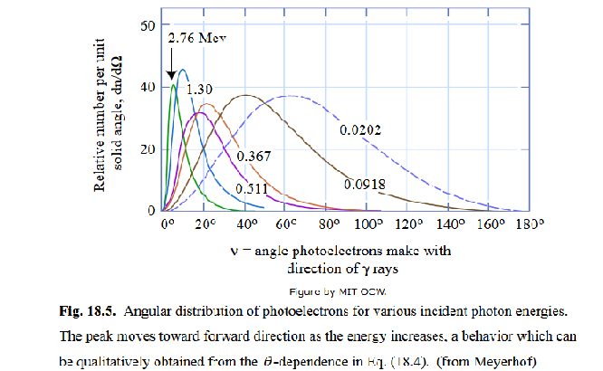
From the answers of anna v and mmainville, it can be seen that the emission of electrons is dependent on the angle of emission of light. But still, the question remains. If the electrons emitted towards anode have enough energy to complete the circuit and again reach the holes in cathode despite the resistance in between, the electrons emitted to the left should have enough energy to come to anode plate via copper wires and again get ejected through anode plate by the virtue of their kinetic energy and reach the cathode plate. In this case too, the current should be zero which is not true. Why?

4 Answers4

5

You have made an assumption that the photo-electrons will be randomly distributed in all directions. This assumption defies the Law of Conservation of Energy and the Law of Conservation of Momentum.

The incoming radiation from source S has momentum and energy that must be conserved. When the incoming radiation hits the cathode surface, some of the energy and momentum is distributed throughout the metal lattice on average inward and at opposite to the normal angle with an energy of the work function. The tensile forces in the metal lattice structure ensure this uniform distribution and the energy is transformed into heat. The remaining energy must be reflected at some angle which conserves momentum and energy. This reflected energy and momentum is carried by the photo-electrons.

So, there are in fact no electrons emitted to the left in your diagram. In fact, photo tubes are generally designed with a curved cathode surface such that the photo-electrons are reflected and focused towards the anode.

It should also be noted that if photo-electrons were being scattered in all directions then we would have a build up of a net positive electric charge at the location of the creation of photo-electrons. Electrons would have to come in to replace this deficiency from somewhere, but this would be inconsistent. The electric field is either pointing towards or away from this point and the average electron drift will be determined by this electric field. It cannot be both at the same time.

In reality, the photo-electrons travel towards the anode and the cathode lead supplies an inrush of electrons to replace the holes created. And thus you have a current flowing through the tube, commutator and ammeter even with the potentiometer set to 0 V.

2

The simple photo electric effect is here

photoel

The electrons appear like an elastic scatter. There are no backward ones because they are absorbed by the metal surface. Electrons in vacuum in motion in one direction are a current by definition of current. As in all scattering experiments with light, there is a beam that hits the cathode. In a photosensivive cathode part of the photons that make up the beam instead of scattering elastically in the scattering angle and rebuild the classical beam in the direction of the scattering angle, will extract an electron.

In particle scattering there is a probability for the electrons to be in all directions but there is an angle of higher probability which the majority of scattered electrons follow. Thus the photoelectrons have a dominant direction. The ones entering back into the metal lattice will neutralize with the hole they left when they scattered. The ones leaving the surface will leave a hole behind, as with normal current flow . This is for gamma rays, but they are photons after all. For low energies there are studies which also give a preferred direction.

angle of phot with electron

In your setup, the same is true, it is the electrons bouncing off the surface of the cathode and hitting the anode a current appears. There is no vacuum when the light is on, because electrons carry the current. Whether there is a voltage drop or not, the geometry of light scattering off the cathode is the same . Applying a voltage allows mapping the effect.

anna v
  • 236,935
2

The electrons start on the cathode. If they go out into the vacuum and then right back to the cathode, well that's where they started, so the net effect is that nothing has happened. These electrons are contributing zero to the current. They are not counterbalancing the electrons that go cathode --> vacuum --> anode.

The only way to counterbalance the electrons that go cathode --> vacuum --> anode is to have other electrons that start in the anode and go anode --> vacuum --> cathode. But the latter doesn't exist, because light is not shining on the anode.

(UPDATE: The question was edited to suggest that electrons are also coming out of the anode into vacuum, even though there's no light shining on the anode. OK, it's true that light is not required to get out electrons---there is such a thing as "field emission", and even field emission at low or zero potential for certain anode materials (e.g. diamond can have negative electron affinity). And the number of electrons exiting the anode is not literally zero, just much much much less than the number of electrons exiting the cathode. The idea in the question edit, i.e. that electrons hit the cathode at high speed, and maintain this speed through the wire, and then come flying out the anode, is very wrong. An electron in a wire experiences something like friction, and loses its high speed probably within nanometers. Anyway, if you think electrons ought to exit the dark anode just as frequently as the illuminated cathode (they don't), maybe you should write a new question saying why you think that. It's kinda far from your original question. I think you'll get better answers that way.)

Steve Byrnes
  • 17,082
0

After your edit, I'm confused. So I replace my original answer to a clarification question.

From your description it appears, as if you are not considering the situation shown in your picture, but rather the symmetric situation shown below: enter image description here Instead of labeling the "plates" as cathode and anode, I used emitter $E$ and collector $C_1$ and $C_2$. Furthermore, I grounded each plate, so that we discuss only the situation described in your question.

Now, all the points you mention make sense:

  • Half of the electrons move to the left and half to the right.
  • There should be no potential difference between the two collectors $C_1$ and $C_2$. However, this is not true for the emitter and one of the collectors. To see this, just remove the ground from all plates.
    1. Initially (=before switching on the light) all three plates $E, C_1, C_2$ will be non-changed.
    2. If we switch on the lights, electrons will be emitted by the emitter $E$ and will be collected by the two collectors $C_1, C_2$. Therefore, negative charges will accumulate at the two collectors $C_1, C_2$, while the emitter will build up a negative charge deficit.
    3. Assuming that no current other than the free electrons flows from or to the three plates, the process will eventually stop, due to build up electric potential. A equilibrium state is reached. Important: Because there is no connection between the three plates, we do not change the charge distribution. We merely capture the information, which plate charges how.

Now, we could measure the potential difference between the three plates and conclude that current will flow only from the emitter (=anode) to the collectors (cathode).

EDIT: In order to get the configuration of the original question we have to omit the plate $C_2$. This does not change the role of the emitter and collector: the collector $C_1$ still accumulates electrons (thereby becoming the cathode) and the emitter $E$ still "donates" electrons (thereby becoming the anode).

Does this situation describe your actual question, or am I completely missing it?

NotMe
  • 9,818
  • 1
  • 15
  • 32