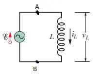
This is just an answer to the second question.
In Situations like these, Potential-difference always means the terminal voltage between two points of the circuit, that is, the voltage you can measure if you take some multimeter, and connect it's ends to the two points.
As you may know, the electric field $\vec{E}$ (a vector field) can always be written as a sum of a conservative field $\vec{E}_c = - \nabla \Phi$ (which doesn't have rotation) and a source-free field $\vec{E}_i$, with $\nabla \vec{E}_i = 0$. This is the helmholtz decomposition. We can easily identify those components as the ones generated by a potential, and the ones induced by changing magnetic fields:
In the following answer I will make the following assumption: We have a circuit whose wires are 100% conducting, their resistance is 0. This results in no electric field components in the wires, as charges can counterbalance any field infinitely fast (I'm ignoring the mass that electrons are having at this point, If you want, you can use it as the additional assumption that electrons don't have mass).
Additionally we assume, that there are no changing fields inside the multimeter, and inside the wires connecting the multimeter to two abitrary points $A$ and $B$ of your circuit.
The measurement of voltage inside your multimeter (voltage in the sense of a length integral of the electromotive force) is then exactly the difference $\Phi(\vec{r}_A) - \Phi(\vec{r}_B)$:
$\int_{\text{closed path}} d\vec{l} \vec{E}_c = 0 = \int_{\text{path from A to B}} d\vec{l} \vec{E}_c + \int_{\text{path from B over Multimeter to A}} d\vec{l} \vec{E}_c \\ = \Phi(\vec{r}_B) - \Phi(\vec{r}_A) + \int_{\text{path over Multimeter}} d\vec{l} \vec{E} \\ = \Phi(\vec{r}_B) - \Phi(\vec{r}_A) - U_{Multimeter} = 0 $
This makes use of the the fact that inside the Multimeter $E = E_c$ because of the absence of changing fields, and the fact that there is no field in the wire connecting the multimeter. In the multimeter, the measured voltage $U_{\text{Multimeter}}$ is the electric force integrated over a certain distance, and that is why $U_{\text{Multimeter}} = \int_{\text{path over Multimeter}}$.
To be very exactly about this, most multimeters (if not all) measure the steady state current that flows through a defined ohmic resistance. This is equal to measuring a field strength over the length of the ohmic resistance, and this is equal to measuring $\int_{\text{path over Multimeter}}$.
Long story short: The Potential difference from $A$ to $B$ is the quantity you can measure when plugging in a multimeter at the two points (That's how you measure it). Furthermore, you have a field called "Potential": $\Phi(\vec{x})$ whose derivatives $ - \nabla \Phi(\vec{x})$ will give you the conservative part of the electric field. The Potential difference is by definition the difference between the values $\Phi(\vec{r}_A)$ and $\Phi(\vec{r}_B$. The Potential difference is not the work done by the electric field along a path from $A$ to $B$, but instead just the work done by the conservative Part of the electric field.
