I am learning about RLC circuits, and I understand that the resonant frequency for a circuit where the capacitor and inductor are in series (and there may or may not be a resistor in series as well to provide 'damping') is equal to $\omega_0=\frac {1}{\sqrt {LC}} $. This means that if a driving voltage is applied, then the maximum amplitude of the current, or maximum chatge/voltage across the capacitor, will occur when the applied voltage is at this resonant frequency. I also read that at the resonant frequency the direction of energy flow is one-dimensional, although I didn't see how the equations showed this and I don't quite understand this point. I think it might be the key to understanding my question below.
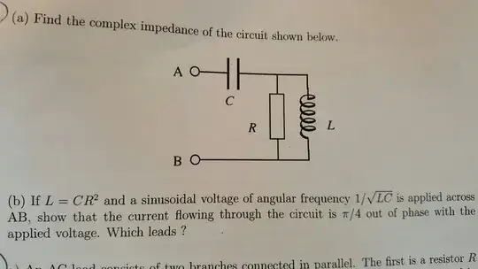
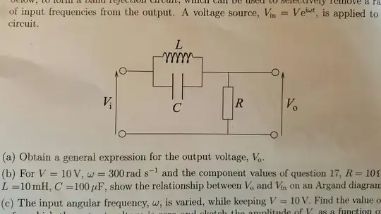
I have now come across slightly different circuits which do not have the inductor and capacitor and resistor in series. Two examples are below
My question is: do these circuits have a 'resonant frequency'? And if so, what does it mean for these circuits to be driven at their resonance frequency?
I have a guess for the second circuit, that the parallel capacitor/inductor circuit can undergo resonance when the driving frequency is equal to $\frac {1}{\sqrt {LC}} $, and then all the source voltage will be across this parallel portion in resonance and there will be no voltage across the resistor. The problem is, that would then mean that there is no current in the circuit! If there is no current in the circuit, surely there cannot be a voltage over the parallel combination?
I am trying to develop both an intuitive feel of what is physically going on in these circuits, and an understanding of how the mathematics relates to this. Any help would be much appreciated!

