At its core, a circuit is all about two things: voltage, and current. When you draw a circuit in a "simpler" form, all you are really doing is rearranging the elements into something more visually appealing, while taking care that the voltage at each end of individual elements, as well as the current flowing through those elements, remains the same.
At the basic level, there are two big "chunks" of circuit to consider. When elements have the same current passing through them, they are in series. When objects have the same voltage at corresponding ends, they are in parallel.
Traditionally, the easiest way to see that something is in series is to draw the elements in a straight line. Consider C2, C3, and C4 in your example. Tracing with your finger, you can see that they all share the same current, and thus are in series. So, when you simplified the setup, you drew them in a straight line.
Likewise, the easiest way to see that objects are in parallel is to draw them on two parallel lines, connected at the top and bottom. You did this with C5 and C6.
In short, you need to be able to recognize when circuit elements are in series or parallel according to the technical definitions. Then, you can re-draw them in whatever orientation you please so long as the "series or parallel" relations are the same.
Now, let's attack the problem from a more qualitative standpoint. Imagine that the wires are stretchy. You are free to move the circuit elements around, and the wire will stretch to follow. However, you aren't allowed to break the wires, or merge them together. As long as you follow these guidelines, you should be able to draw equivalent circuits very easily.
Personally, I like to draw several intermediate steps. This way, I take care of the most obvious combinations first, and in turn the remaining combinations become easier to see. I have included an example below, which I took as a subsection of the problem you presented.
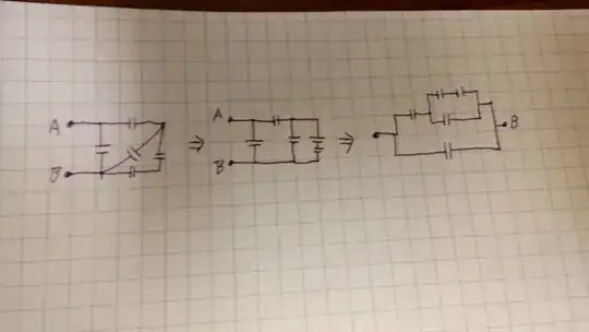
To me, the most obvious thing I saw was that the corner elements were in series. Then, this series was in parallel with the diagonal. I put this together, and stretched the wires into the form in the middle picture.
Now, I note that the three capacitors I just moved are in series with the top capacitor, and that in turn this new unit is in parallel with the remaining capacitor. So, I stretch the wires and draw the configuration in a more typical manner.


