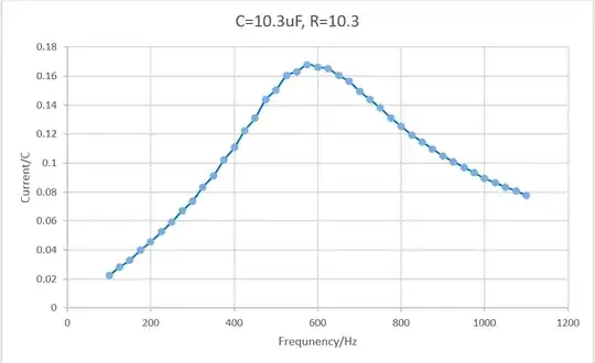
When I was measuring the current with varying frequency of an series RLC circuit, I noticed that the graph produced is asymmetric:
Is there any reason for this? (inductance=8.29mH) The Q-factor is 2.75 (3 s.f.)
When I was measuring the current with varying frequency of an series RLC circuit, I noticed that the graph produced is asymmetric:
Is there any reason for this? (inductance=8.29mH) The Q-factor is 2.75 (3 s.f.)
Probably stray (parasitic) capacitance or inductance. Inductors also have capacitance, and capacitors have inductance. And resistors have both. So in terms of transfer functions, your circuit probably has poles and zeros at frequencies higher than the primary resonance. This causes energy to spill into the higher frequency band.
Try measuring each component individually on an impedance bridge to test that hypothesis. And if you get measures, try estimating your circuit response with the 'additional' components and build a model to see if it matches your original response.