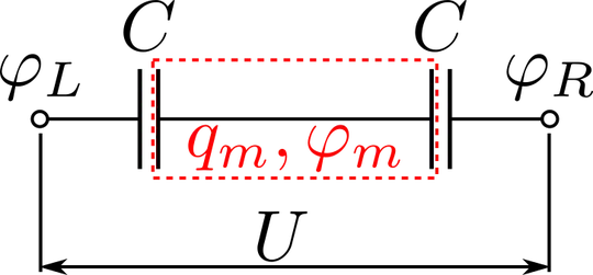
I am trying to find equivalent circuit for a circuit composed of interconnected capacitors when isolated pieces of conductor may carry nonzero electric charge, and I have been struggling with this problem for some time now.
I want to understand what is the equivalent circuit for the situation depicted below. The only difference from the usual series capacitor circuit is the nonzero charge $q_m$ trapped on the piece of conductor marked with a dashed red square.
Such situation can be created by performing the following steps:
(1) A capacitor (capacitance $C$) is initially charged to hold some electric charge $q_m$;
(2) The capacitor is then connected in series with an identical, uncharged capacitor. The charge $q_m$ becomes trapped between the two capacitors;
(3) Finally, some voltage $U$ is applied across the circuit.
This is what I did to find equivalent circuit for the depicted situation:
Let's assume that electric potential of the leftmost electrode is $\varphi_L$, and electric potential on the rightmost electrode is $\varphi_R$, such that $U = \varphi_R - \varphi_L$. Electric potential of the charged piece of conductor in the middle is $\varphi_m$. Electric charges stored on the leftmost and rightmost plates are:
$q_L = C (\varphi_L-\varphi_m)\\ q_R = C (\varphi_R-\varphi_m)$
The total charge of the middle conductor is $q_m$, and therefore:
$q_m = C (\varphi_m - \varphi_L + \varphi_m - \varphi_R)$.
The potential $\varphi_m$ can now be excluded from the expressions for $q_L,q_R$, which yields:
$q_L + \frac{q_m}{2} = \frac{C}{2} (\varphi_L-\varphi_R)\\ q_R + \frac{q_m}{2} = \frac{C}{2} (\varphi_R-\varphi_L)$
Now, these are equations for charge stored on a capacitor with capacitance $C/2$, when the voltage across the capacitor is $\varphi_R-\varphi_L \equiv U$. It would seem that the seach for the alternative circuit is over now. However, electrostatic energies of the two circuits differ: for the original circuit it is:
$W_{orig} = \frac{C}{4}(\varphi_R-\varphi_L)^{2} + \frac{q_m^2}{4C}$,
while energy of the "equivalent" circuit is:
$W_{eq} = \frac{C}{4}(\varphi_R-\varphi_L)^{2}$.
Therefore the single capacitor $C/2$ can not be equivalent to the original series circuit!
Instead it seems to me that the original circuit may be equivalent to a set of two independent circuits, where one of them is the $C/2$ capacitor connected to a voltage source, and the other one is a piece of isolated conductor with capacitance $2C$ and charge $q_m$.
So far I have not found any books confirming or contradicting my solution or the physical interpretation. Do you have any ideas, where I should look for explanation? Or maybe you can confirm my line of thought or point out what is wrong with it? Any help will be much appreciated!
