A lot of problems of this type can be solved by rearranging the circuit into a more user friendly form.
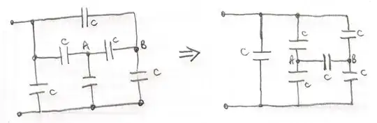
By symmetry you can say $V_{AB}=0$ and so you get $2C$ as the equivalent capacitance.
There is a method for solving such network problems which goes back to first principles and is equivalent the using Kirchhoff’s law which are based on the conservation of charge and the conservation of energy.
The first thing to do is draw the circuit and label it.
In this case I missed out the left hand capacitor because it will just be in parallel with the equivalent capacitance of the circuit which is left.
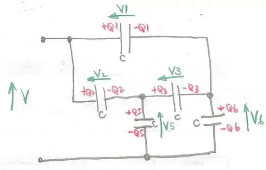
Label the charges $+Q_1, -Q_1$ on each of the capacitors and the voltages $V1$ with an arrow to indicate direction of increased potential.
Looking at the diagram the equivalent capacitance of the network will be $\frac{Q_1+Q_2}{V}$ so you need to find $Q_1+Q_2$ in terms of $V$ and $C$.
For each capacitor there is a relationship of the form $Q_1=CV_1$.
Looking at the charges first noting that the total charge at each node where only capacitors are connected must be zero.
$-Q_2+Q_3+Q_5 = 0$ and $Q_3-Q_1+Q_6 = 0$
Adding these two equations together $\Rightarrow Q_1+Q_2-Q_5-Q_6= 0 \Rightarrow V_1+V_2=V_5+V_6$
Now looking at the voltages:
$V=V_1+V_6$ and $V= V_2+V_5$
Adding these two equations together
$\Rightarrow 2V =V_1+V_2+V_5+V_6 \Rightarrow 2(V_1+V2) \Rightarrow \dfrac {2(Q_1+Q_2)}{C}$
So the equivalent capacitance is $\dfrac{Q_1+Q_2}{V} = \dfrac{CV}{V} = C$
For the whole circuit the equivalent capacitance is $2C$.


