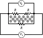
Both voltmeters are indeed connected to the same endpoints, but if the system contains changing magnetic fields then it is no longer true that this implies that they must read the same voltage.
Instead, their difference $V_2-V_1$ measures the line integral of the electric field along the outermost wire loop (i.e. the one including both voltmeters and no resistors), and this in turn is specified by Faraday's law of magnetic induction to be the rate of change of magnetic flux inside the loop:
$$
V_2-V_1=\oint_C \mathbf E\cdot \mathrm d \mathbf r=-\frac{\mathrm d}{\mathrm dt}\iint_{\text{int}(C)}\mathbf B\cdot \mathrm d\mathbf S=-\frac{\mathrm d \Phi}{\mathrm dt}.
$$
If the rate of change in magnetic flux is nonzero, $V_2$ and $V_1$ will be different.
To find out what this difference is, you need more information on $\frac{\mathrm d \Phi}{\mathrm dt}$. This can be obtained from the inner loop (i.e. the one with three resistors), as there the EMF is balanced by the ohmic voltage of the resistors, from which you can find the current in that loop. Once you do that, applying Faraday's law to the two outer loops (with a mix of voltmeters and resistors, but no magnetic field) will give you the measured voltages.