2

So,i was studying from some lecture notes from MIT's open course program,and i stumbled across this example enter image description here

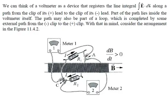
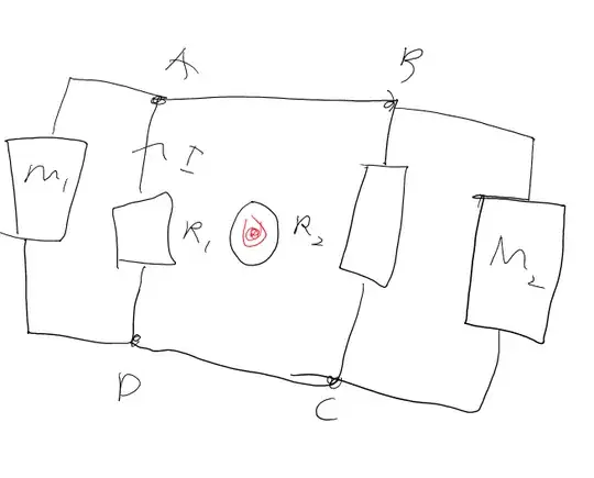
The example says:The solenoid is so long that its external magnetic field is negligible. Its cross section is 20 cm^2 in area, and the field inside is to the right and increasing at the rate of 10^-2 T/s . Two identical voltmeters are connected as shown to points A and C on the loop, which encloses the solenoid and contains the two resistors of 50 Ohm each one. This gives us the readings of VM1=-10μV and VM2=10μV(calculations will be shown afterwards).Now,this is kind of weird,as the two voltmeters give us different measurements for the same point,but this is all included in the theory of induction due to changing magnetic flux(the integral of E.dS depends on the actual path).Things get weirder in this situation: I want to change the resistors to study what changes to the voltmeter's readings.I make R1=40Ω and R2=60Ω.
This gives us:enter image description here
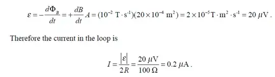
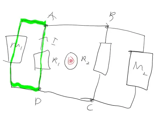
For VM1 we consider the loop that encloses R1 and VM1 and it gives us a reading of IR1=0.2*40=8μV and the first voltmeter is showing -8μV because the voltage at A is bigger than that of C(as shown in the image)because of the direction of the flow of the current. 
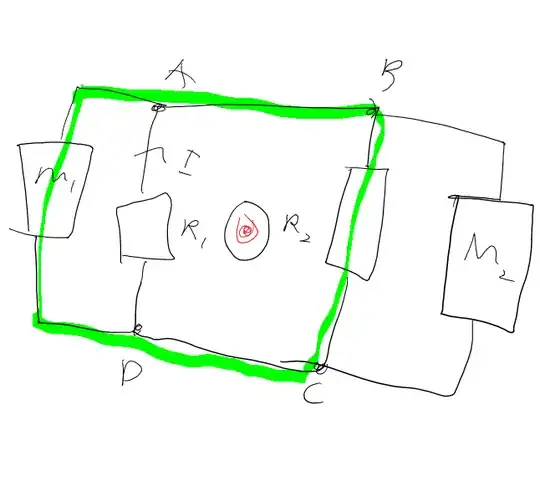
But VM2 gives us IR2=-12μV(the negative sign due to the flow again).
Now,this i can not understand!We measure the same points,but we have different results!It is one thing to just get an opposite sign,but another thing to get two totally different numbers!
Can anybody please explain this to me?

Qmechanic
  • 220,844

1 Answers1

2

The key to this question is the position of the voltmeter and the flux it contains. Consider the diagram below: enter image description here

Let us say we are finding the voltage between A and D using the volt meter $M_1$. We can do this using one of two loops:

  1. One going straight from A to D. enter image description here
  2. The one going from A to B to C then to D. enter image description here

The first one will give an answer of $V_1=-IR_1$ since there is no flux passing thru the circuit we are considering (that including M1 and $R_1$). When we do it around the other loop then we must include the induced emf. So using Kirchoff's voltage law around this loop [$M_1$ and $R_2$] (which is valid if we include the induced emf). Then we get: $$-V_1+IR_2=\epsilon$$ but $\epsilon=I(R_1+R_2)$ so: $$-V_1=IR_1$$ we get the answer we got before. An analogous process can be done for the voltmeter on the second side. Such that: $$V_2=IR_2$$ [$V_1$ denotes the reading on voltmeter $M_1$ and $V_2$ that on $M_2$] The point is when we have non-conservitavie fields and when stating the voltage difference between two points we must also state where the voltmeter is positioned, the answer depends on its location, due to the induced emf. Note that for any loop we go round for a given voltmeter location then they all agree on the location (it would be very strange if we got a contradiction here). I hope this answers your question.

[P.s. Sorry for the poor diagrams, the circle in the middle is ment to be a solinode.]