It might be helpful to consider the electronic dynamics involved and be aware of the difference to a circuit's parameters that the two configurations (series and parallel) result in electronically.
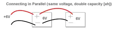
Two power sources in parallel will together output the same voltage as they would if they were the only power source present but the total current flow (measured in amps) of the two power sources is added together (if the two sources put out equal amounts of voltage then this means the entire circuit's amperage is doubled but the voltage remains the same).
In series, just the opposite is true - the amperage supplied to the circuit by two power sources is the same amperage as would be supplied by either source alone and the total voltage is then doubled (again, assuming the two sources are of equal size and capacity).
So it's a tradeoff when you combine two or more power sources, something must change or there'd be no point in doing it, logically something should increase. The tradeoff is that something is either current or voltage and which one it is, is determined by which configuration the power sources are in.
Keep in mind, these values aren't necessarily doubled, it only works out that way when both power sources are identical to each other.
Editing in the technical details of electronics involved for validation of my answer
   Kirchoff's Voltage Law: (parallel circuit)
   "The algebraic sum of all voltages around any closed loop circuit must equal 0".
   (A consequence of the conservation of energy).

   Let V = voltage
   V(source1) + [-V(source2)]  = 0
   V(total) = V1 = V2
   I(total) = I1 + I2
And
   Kirchoff's Current Law : (series circuit)
   "The algebraic sum of all currents entering and exiting a node must equal 0".
   (A consequence of the conservation of charge).

   Let current=I
   I(entering) + [-I(exiting)] = 0
   I(total) = I1 = I2
   V(total) = V1 + V2
There's what's known as :
   ideal voltage source - has zero internal resistance/impedance so that
   changes in load resistance/impedance will not change the voltage
   supplied.

   (see Thevenin's Theorem). This is your parallel 2 source circuit.
And
   ideal current source - has infinite internal resistance/impedance
   (and therefore zero source admittance since admittance is the reciprocal
   of impedance or resistance) so that changes in load impedance/resistance
   will not change the current supplied.

   (see Norton's Theorem). This is the series 2 source circuit.
Further information:
   Thevenin's Theorem :
   "For linear electrical networks, any combination of voltage sources,
   current sources, and resistors with two terminals is electrically
   equivalent to a single voltage source V and a single resistor R.
   Any two-terminal, linear bilateral dc network can be replaced by an
   equivalent circuit consisting of a voltage source and a series resistor.
   The voltage source is equal to the potential difference between the two
   terminals connected to these terminals. The series resistance (or
   impedance) is the equivalent resistance/impedance looking into the two
   terminal ports with all the power sources within the pair inactive".


   Or worded differently to reflect the ideal source concepts:

   "Any electrical signal source is equivalent to an ideal voltage source in
   series with a source impedance".
And
   Norton's Theorem :
   "Any two terminals of a network composed of linear passive and active
   circuit elements may be replaced by an equivalent current source and a
   parallel resistance. The current of the source is the current measured in
   the short circuit placed across the terminal-pair. The parallel
   resistance is the equivalent resistance looking into the terminal-pair
   with all the independent power sources inactive".

   Or worded differently to reflect the ideal source concepts:

   "Any electrical signal source is equivalent to an ideal current source in
   parallel with a source admittance".