Do static charge in a strong insulator flow to a weaker insulator when both stay in contact with each other? For example, when an insulator weaker than air placed in a medium of air, would the static charges on the insulator be absorbed to the air slowly and finally the insulator becomes neutral? If so then what is the rate of flow from the insulator to air?
Asked
Active
Viewed 286 times
2 Answers
1
The Triboelectric effect is the process through which materials can become electrically charged through friction when they come in contact with other different materials.
These materials do not have to be insulators for this effect to take place however if they are good conductors the charge will usually flow away.
There is a series of materials ranging from those that become positively charged to those like to remain neutral to those that become negatively charged. This series is independent of a materials conductivity. With aluminium, steel and silver being good conductors and wool and polystyrene being good insulators in between them on the list.
user288447
- 1,954
1
When you put a charged insulator in air, the reason you lose charge is mostly due to humidity in the air. I gave details of this mechanism in a recent answer to a related question: https://physics.stackexchange.com/a/130988/26969
The curves in the referenced paper (some of which I reproduce in that answer) show you how the leakage current is a function of the relative humidity - conversely if you know the amount of charge, you can compute the rate of charge loss using these curves.
For example, if you had a sphere of radius 10 cm charged to 100 kV, you would have a charge of
$$\begin{align}\\ Q &= 4\pi\epsilon_0 r V\\ &= 4 \pi \cdot 8.85\cdot 10^{-12} \cdot 0.1 \cdot 10^5\\ &= 1.11 \mu C\end{align}$$
So the surface charge density (charge / area) would be
$$\begin{align}\\ \sigma &= \frac{Q}{4\pi r^2}\\ &=\frac{\epsilon_0 V}{r}\\ &= 8.85 \mu C / m^2 \end{align}$$
Now the leakage data we will use came from a setup with 40 parallel plates with alternating voltages, so 39 pairs of gaps of 0.66 mm with up to 1.5 kV across them, and a surface area of 25.4 $cm^2$. That makes the highest electrical field $E = 1.5/0.66 = 2.3 MV/m$ and the area 990 $cm^2$. For a relative humidity of 50%, this setup produced about 10 nA of leakage current (reading from the plot reproduced from the paper referenced in the above answer):
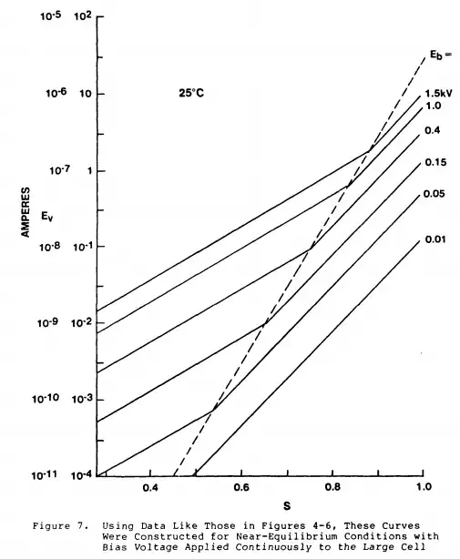
Now the sphere above actually has an electrical field at the surface of
$$E=\frac{Q}{4\pi\epsilon_0 r^2}=\frac{V}{r}=1MV/m$$
translating back to the given setup, that corresponds to an applied voltage (across the 0.66 mm gap) of 660 V, and a leakage current (hard to read a log scale without subdivisions) of maybe $\frac{3 nA}{990 cm^2} = 30 nA/m^2$. For our sphere with a surface area of $0.04\pi m^2$ this gives a leakage current of about 3 nA - or about 0.3% of the charge on the sphere per second.
I gave the above calculation as an example of how to interpret / use the tables given - obviously the answer for your geometry will be somewhat different. Note that regions of higher curvature will have higher fields, and initially greater leakage - but this will not last since charge will not flow on the insulator; so soon, the electric field will even out.